This collection includes power supplies suitable for almost any HeNe tube or laser head with an optical output power from .5 to 35 mW - and beyond. See the section: HeNe Laser Power Supply Selection Guide to identify the one (or more!) that may be most suitable for your collection of HeNe tubes as-is or with minor modifications. And, most of these circuits can be easily modified for your specific needs: For example, a very high power HeNe tube or a weird laser requiring multiple power supply feeds and separate starters
CAUTION: Although not explicitly shown in some schematics, accessible parts of the power supply and laser head should be connected to earth ground via a three-prong power cord. This protects against a dangerous shock hazard should there be a fault condition and also eliminates any possibility of even a slight tingle due to capacitive coupling of high voltages. Where such a problem is detected with an existing power supply, there is likely an insulation or wiring problem in either the supply or laser head which should be corrected. If a ground is simply added to the laser head case, the power supply may fail due to a problem elsewhere.
CAUTION: Where a ground was not shown on some of the commercial HeNe laser power supplies, its schematic may show one in the logical place assuming an Alden-type (2 wire) connection to the laser head. However, a few commercial power supplies used 3 wires with a separate ground.
WARNING: There are so many complete HeNe laser power supply schematics in this one document that their combined mass may cause a singularity to form inside your computer. :-) The lawyers made me include this statement - honest. ;-)
Note: For an explanation of the meanings of various designations like X, Y, HV+, Tube-, etc., used in these schematics, see the section: Notation used in HeNe Laser Power Power Supply Diagrams and Schematics.
           Desig-    Power   Regu-   Modu-  <-- Tube Output Power (mW) -->
           nation    Input  lation  lation   - .5 1 2 3 5 7 10 15 25 35 +
         -----------------------------------------------------------------
          ES-HL1      AC      -        -     ********
          LS-220      AC      L        -           ******
          ML-360      AC      -        -     ********
          ML-420      AC      -        -         ******
          ML-620      AC      L        -     ******
          ML-660      AC      L        -     *******
          ML-920      AC      L        -           ****
          SP-130      AC      -        -         ****
          SP-155      AC      L        -     ******
          SP-132      AC      -        -         *****
          SP-132M     AC      -        -         *****
          SP-233      AC      -        -         *****
          SP-233M     AC      -        -         *****
          SP-234      AC      -        -           *****
          SP-235      AC      -        -           *****
          SP-247      AC      L        -            ********
          SP-248      AC      L        -            ****
          SP-249      AC      L        -             ****
          SC-760      AC      L        -               ***
          JD-PS1      AC      L        -          *****
          AT-PS0      AC      L        -        ***
          AT-PS1      AC      L        -          ***
          AT-PS2B     AC      L        -              *******
          AT-PS2A-X   AC      L        V            *****
          SP-255      AC      L        -                    *******
          SP-256      AC      L        -                ********
          SP-207      AC      L        -                       *********
          SP-261      AC      S        -                             ****
          LP-HL1      AC      L        -     *****
          LP-HL2      AC      L        -     *****
          HK-HI1      AC      -        V     *****

          SG-HL1      AC      -        -        *********
          SG-HL2      AC      -        -                ********
          SG-HL3      AC      -        -                  ***********
          KC-HL1      AC      -        -              ************
          TF-HL1      AC      L        -                       *********

          IC-HI1      DC      S        P     ******
          IC-HI2      AC      S        P        ******
          IC-HI3      DC      S        -     ******
          EG-LPS1     DC      -        -     ******
          ML-600      AC      D        -      ******
          ML-800      AC      D        -      ******
          ML-811      DC      S        -     ******
          ML-855      AC      D        -             *****
          ML-869      AC     D/L       V         ****
          HU-HL1      DC      D        -           ****
          YA-234      DC      S        -                ***
          LD-BS1      DC      S        -     *******

          SG-HI1      DC      -        -     ********
          SG-HI2      DC      -        -     ********
          SG-HI3      DC      S        -     ********
          SG-HI4      DC      -        -     ********
          SG-HM1      DC      S        -     **************
          SG-HM2      DC      S        -     ********

          DP-HI4      DC      -        -     ********
          KC-HI1      DC      -        -     ********
          YA-HI1      DC      -        -     ******
Notes:
Many of these designs are quite old since modern commercial units tend toward inverter designs since they can be more compact and have higher efficiency. Unfortunately, modern inverter types are nearly always potted in Epoxy and impossible to disassemble and analyze. However, AC Line operated power supplies will drive HeNe tubes just as well as fancy inverters and are somewhat easier to construct and troubleshoot (especially for high power designs).
The line side circuitry is not shown for any of these. See the section: AC Input Circuitry for HeNe Laser Power Supplies for details.
Those with "Sam's" in the title were built using mostly scrounged parts like tube type TV power transformers that had been minding their own business in various storage cabinets often for many many years. My total cost for the remaining components for each power supply was generally not over $5.
They are presented in approximate order of output capability which is why the sequence of manufacturer and model number may appear somewhat random. :)
Estimated specifications (ES-HL1):
This is the power supply I traced out and measured which is in an Edmund Scientific 0.5 mw. Laser circa probably around 1975. I bought a 1 mW. tube (1986) when the old one broke. It is still running just fine. I think it is a rather clever design and I don't think they come any simpler.
       X                   C5                      C7
       +-------------------||-----------+----------||-----------+---o HV+
       |                       D7  D8   |  D9  D10     D11 D12  |   R5
       |                    +--|>|-|>|--+--|>|-|>|--+--|>|-|>|--+--/\/\--+
       |  D1  D2  D3   Y    |          C6           |              18K   |
   +---+--|>|-|>|-|>|--+----+----------||-----------+              1W    / R6
||(    |               |    |                                            \ 33K
||(    |          C1 +_|_   / R1                                         / 1W
||(    |       4.7uF  ---   \ 1M                                         |
||(    |        450V - |    /                                            / R7
||(    |               |    |                                            \ 33K
||(    |               +----+ W   Transformer: 650 VRMS, 20 mA           / 1W
||(    |               |    |       (primary not shown)                  |
||(    |          C2 +_|_   / R2                                         / R8
||(    |       4.7uF  ---   \ 1M                                         \ 33K
||(    |        450V - |    /                                            / 1W
||( T  |               |    |     D1-D7: 1N4007 or similar               |
   +-------------------+----+                                            / R9
       |               |    |                                            \ 33K
       |          C3 +_|_   / R3  C1-C4: 4.7uF, 450V                     / 1W
       |       4.7uF  ---   \ 1M  C5-C7: .001uF, 2kV                     |Tube+
       |        450V - |    /                                          .-|-.
       |               |    |     R1-R4: 1M, 1W                        | | |
       |               +----+ Z   R5-R9: (ballast, 18K+4x33K, 1W)      |   |
       |               |    |                                      LT1 |   |
       |          C4 +_|_   \ R4                                       |   |
       |       4.7uF  ---   / 1M                                       ||_||
       |        450V - |    \                                          '-|-'
       |               |    |                                            |Tube-
       +--|<|-|<|-|<|--+----+--------------------------------------------+---o
          D4  D5  D6                                                        HV-
Note that there are no equalizing resistors across the 1N4007s. While I have
been building similar supplies without them, the use of 10M resistors across
each diode to equalize the voltage drops is recommended.
The 650 V transformer output feeds a voltage doubler (D1 and D2 and C8 to C11) resulting in about 1,750 V across all the electrolytics. (Slightly less than 2 times the peak value of 650 VRMS.) The voltage multiplier consisting of D7 to D12 and C5 through C7 generates up to 6 times the transformer's peak voltage or around 5,300 V (the actual value will depend on various factors including stray capacitance and other losses). See the section: Voltage Multiplier Starting Circuits for a description of its design and operation.
The 150K ballast resistor is actually constructed from 4 - 33K resistors and one 18K resistor in series. It doesn't have to be, but this is convenient and allows the ballast to be changed easily (or just tap off the appropriate point for your tube. My notes show 600 V across the ballast resistor-combo.
The ballast resistor should be located close to the tube with as short a lead as possible and as little capacitance to surroundings as possible. The tube needs to see a high impedance source. This isn't super critical, but keep the wire down to 1 to 3 inches and the first few resistors away from any case or ground material.
Since there is no active regulator, the tube current will depend on the power line voltage and other factors like temperature. However, the relatively large ballast resistor in this power supply should minimize excessive variation.
There is also a GAMMEX HeNe laser power supply that appears virtually identical to this one. I don't have a sample but from a photo of the circuit board, the only obvious difference would appear to be the use of 6, 27K, 2 W resistors for the ballast. All the other parts and even the part values appear identical. So GAMMEX probably copied the circuit and adjusted the value of the ballast resistance until the desired current was obtained. :)
This diagram is not yet complete in the area of the control circuit in the lower right corner since it is difficult to trace it without removing the PCB. In particular, there are at least two tantalum caps and other components which contribute to the low noise performance.
The secondary voltage of T1 was guessed. :) There were no part numbers on the PCB so these are arbitrary.
The HeNe laser tube and its ballast resistor are not shown here. The ballast is a single 7 or 10 W resistor mounted on standoffs in the laser head. But there is also a thermal regulator in series with the anode of the tube. It implements a closed-loop feedback scheme using only the anode current with no other connections to stabilize the temperature of the OC mirror.
      X            C7                       C8              C9
      +------------||----------------+------||-------+------||-------+   HV+ o
      |                         CR3  |  CR4     CR5 |   CR6     CR7  |  CR8  |
      |                      +--|>|--+--|>|--+--|>|--+--|>|--+--|>|--+--|>|--+
T1    |  CR1   Y      R7 55  |      C10      |      C11      |      C12      |
   +--+--|>|---+----+--/\/\--+------||-------+------||-------+------||-------+
||(   |        |    |
||(   |   C1 +_|_   / R1                             +---------+----+---o Tube-
||(   | 10uF  ---   \ 499K  T1: 1,200 VRMS, 20mA    _|_        |    |
||(   | 500V - |    /         (primary not shown)   _V_ CR9    /    |
||(   |        |    |                                |      R7 \    |
||(   |        +----+       CR1-CR6: SCM60, 6kV      +    120K /    |
||(   |        |    |                               _|_        |  |/ C Q1
||(   |   C2 +_|_   / R2    C1-C6: 10uF, 500V       _V_ CR10   +--|    D40V4
||(   | 10uF  ---   \ 499K  C7-C9: 470pF, 6kV       _|_        |  |\ E
||(   | 500V - |    /       C10-C12: 6800 pF, 6kV  ////     R8 /    |
||(   |        |    |                             1N4007  120K \    |
||(   |        +----+                              (x2)     2W /    |
||(   |        |    |                                          |  |/ C Q2
||(   |   C3 +_|_   / R3                                       +--|    D40V4
||(   | 10uF  ---   \ 499K                                     |  |\ E
||(   | 500V - |    /                                       R9 /    |
||(   |        |    |                                     120K \    |
   +--|--------+----+                                       2W /    |
      |        |    |                                          |  |/ C Q3
      |   C4 +_|_   / R4                                       +--|    D40V4
      | 10uF  ---   \ 499K                                     |  |\ E
      | 500V - |    /                                      R10 /    |
      |        |    |                                     120K \    |
      |        +----+                              R11 27.2K   |  |/ C Q4
      |        |    |                              +---/\/\----+--|    D40V4
      |   C5 +_|_   / R5                           |           |  |\ E
      | 10uF  ---   \ 499K                         |         |/ E   |
      | 500V - |    /                     +--------+---------|      |
      |        |    |                     |   +---+       Q5 |\ C   |
      |        +----+               ZD1  _|_, |   | ZD2  PNP   |    |
      |        |    |            1N4099 '/_\  |  _|_,          +----+
      |   C6 +_|_   / R6           6.8V   |   | '/_\  R12           |
      | 10uF  ---   \ 499K         (x2)   +---+   |  5K 1W          |
      | 500V - |    /                      Adjust +---/\/\----------+
      |        |    |                             |    |
      +--|<|---+----+-----------------------------+----+
         CR2
Estimated specifications (ML-360):
This power supply is almost identical to the ES-HL1, above, and may indeed just be a variation on it since Edmund Scientific very likely sold Metrologic lasers or clones under their own brand name.
I replaced the original quite dead soft-seal HeNe tube with a Uniphase 098-2 which is rated at 2 mW so the output is probably twice that of the original laser. No changes were required to satisfy the 4.5 to 5 mA current recommended for the 098-2. The set of ballast resistors is way overdesigned, power-wise, so there should be no problem with overheating. The only thing marginal may be the starting voltage but the 098-2 starts instantly.
                                                                       HV+ o
      X                   C5                              C7               |
      +-------------------||---------------+--------------||---------------+
      |                       D7  D8  D9   |  D10 D11 D12     D13 D14 D15  |
      |                    +--|>|-|>|-|>|--+--|>|-|>|-|>|--+--|>|-|>|-|>|--+
      |  D1  D2  D3   Y    |              C6               |               |
   +--+--|>|-|>|-|>|--+----+----+---------||---------------+            R5 /
||(   |               |    |    |                                     3.9M \
||(   |          C1 +_|_   / R1 |                                          /
||(   |         5uF  ---   \ 1M |    R6    R7    R8    R9    D16 D17 D18   |
||(   |        450V - |    /    +---/\/\--/\/\--/\/\--/\/\---|>|-|>|-|>|---+
||(   |               |    |                                               |
||(   |               +----+     Transformer: 700 VRMS, 20 mA              |
||(   |               |    |       (primary not shown)                     |
||(   |          C2 +_|_   / R2                                            |
||(   |         5uF  ---   \ 1M                                       Tube+|
||(   |        450V - |    /                                             .-|-.
||( T |               |    |     D1-D18: 1N4007                          | | |
   +------------------+----+                                             |   |
      |               |    |                                             |   |
      |          C3 +_|_   / R3  C1-C4: 5uF, 450V                    LT1 |   |
      |         5uF  ---   \ 1M  C5-C7: .001uF, 2kV                      |   |
      |        450V - |    /                                             |   |
      |               |    |     R1-R4: 1M, 1/2W                         ||_||
      |               +----+ Z   R6-R9: (ballast, 18K+3x33K, 2W)         '-|-'
      |               |    |                                          Tube-|
      |          C4 +_|_   \ R4                                            |
      |         5uF  ---   / 1M                                            |
      |        450V - |    \                                        HV- o--+
      |               |    |                                               |
      +--|<|-|<|-|<|--+----+-----------------------------------------------+
         D4  D5  D6
Note that there are no equalizing resistors across the 1N4007s. While I have been building similar supplies without them, the use of 10M resistors across each diode to equalize the voltage drops is recommended.
Also, the measured voltage across the filter capacitors exceeds their 450 VDC ratings until the laser tube starts, and then drops down a bit. But that is still beyond marginal in my book. Slight differences in the equalizing resistor values and/or leakage of the caps could result in a mess. Having said that, I haven't seen any of these with blown caps.
The only notable difference between ML-360 and ES-HL1 is that the starting voltage is fed to the anode of the HeNe tube via a set of blocking diodes in parallel rather than the more common series arrangement.
I was given another nearly identical power supply with the only difference being that there were only 2 diodes in series instead of 3 diodes for each stage of the voltage multiplier. I do not know what laser this came from.
Estimated specifications (ML-620):
I haven't been able to locate cross references for the ITT992 diodes and M639 transistors but would expext that 1N4007s and MJE3439s would be satisfactory substitutes.
The factory setting for HeNe tube current is about 4.5 mA. However, this can be adjusted by changing the value of R5 or R6. It works nicely with the typical 6" long 0.5 to 1.5 mW barcode scanner HeNe laser tube as a replacement since in all likelihood the original soft-seal tube will be very dead in any sample you acquire. However, the value of R5 or R6 may need to be changed to set the current at the optimal value for the replacement tube to maximize output power and tube life. Typical 6" tubes only require 3 to 3.5 mA.
      X               C5                          C7                      HV+
      +---------------||---------------+----------||-----------+           o
      |                       D7  D8   |  D9  D10     D11 D12  |  D13  D14 |
      |                    +--|>|-|>|--+--|>|-|>|--+--|>|-|>|--+--|>|-|>|--+
      |  D1  D2  D3   Y    |          C6           |          C8           |
   +--+--|>|-|>|-|>|--+----+----------||-----------+----------||-----------+
||(   |               |    |                         R12    R11    R10     |
||(   |          C1 +_|_   / R1                 +----/\/\---/\/\---/\/\----+
||(   |       4.7uF  ---   \ 1M                 |
||(   |        450V - |    /                    |   +------------+ Tube-
||(   |               |    |                    +---|-         ]-|----+----+
||(   |               +----+                  Tube+ +------------+    |    |
||(   |               |    |                             LT1       R9 /    |
||(   |          C2 +_|_   / R2                                   56K \    |
||(   |       4.7uF  ---   \ 1M  T1: 700 VRMS, 25mA            R8  2W /    |
||(   |        450V - |    /       (Primary not shown)      56K 2W    |  |/ C
||( T |               |    |                           +-----+--/\/\--+--| Q1
   +------------------+----+     D1-D14: 1N4007        |     |           |\ E
      |               |    |     R10-R12: 12K,2W    R7 /    _|_.D16        |
      |          C3 +_|_   / R3                    27K \   '/_\ 1N758      |
      |       4.7uF  ---   \ 1M  Q1,Q2: MJE3439        /     |             |
      |        450V - |    /                           |     |           |/ C
      |               |    |                           +-----|-----------| Q2
      |               +----+ Z                         |     |           |\ E
      |               |    |                           |     |             |
      |          C4 +_|_   \ R4                   D15 _|_.   +-------------+
      |       4.7uF  ---   / 1M                 1N758'/_\                  |
      |        450V - |    \                           |    +---+     R6   |
      |               |    |                           |    |   v    1.2K  |
      +--|<|-|<|-|<|--+----+---------------------------+----+-/\/\---/\/\--+
         D4  D5  D6                                         R5 600         |
                                                                       HV- o
Estimated specifications (ML-920):
      X         C9             C10             C11
      +---------||------+-------||------+-------||------+
      |            CR3  |  CR4     CR5  |  CR6     CR7  |  CR8
      |         +--|>|--+--|>|--+--|>|--+--|>|--+--|>|--+--|>|--+--o HV+
      |         |               |               |               |
      |         |    +----||----+-------||------+-------||------+
T1    |   CR1   |Y   |   C12           C13             C14      |
   +--+---|>|---+----+                                      33K /
||(   |         |    |         T1: 900 VRMS, 15mA            2W \ Rb1
||(   |    C1 +_|_   / R1       (primary not shown)             /
||(   | 4.7uF  ---   \ 510K                                     |   Rb2
||(   |  450V - |    / 1/2W    CR1-CR9: 3x1N4007                +--/\/\--+
||(   |         |    |                                            33K 2W |
||(   |         +----+         C1-C8: 4.7uF, 450V                   Rb3  |
||(   |         |    |         C9-C14: 1nF, 3kV                 +--/\/\--+
||(   |    C2 +_|_   / R2                                       | 33K 2W
||(   | 4.7uF  ---   \ 510K    R1-R8: 510K,1/2W                 |Tube+
||(   |  450V - |    / 1/2W    R9-R11: 68K, 1W                .-|-.
||(   |         |    |                                        |   |
||(   |         +----+         Q1-Q3: MJE340T                 |   |
||(   |         |    |                                        |   |
||(   |    C3 +_|_   / R3                                 LT1 |   |
||(   | 4.7uF  ---   \ 510K                            2-3 mW |   |
||(   |  450V - |    / 1/2W                                   |   |
||(   |         |    |                                        |   |
||(   |         +----+                                        ||_||
||(   |         |    |                                        '-|-'
||(   |    C4 +_|_   / R4                                       |Tube-
||(   | 4.7uF  ---   \ 510K                                +----+
||(   |  450V - |    / 1/2W                                |    |
||(   |         |    |                                 R10 /    |
   +--|---------+----+-----------------------------+   68K \    |
      |         |    |                             |    1W /    |
      |    C5 +_|_   / R5                          |       |  |/ C Q1
      | 4.7uF  ---   \ 510K                        |       +--|  MJE340T
      |  450V - |    / 1/2W                        |       |  |\ E (NPN)
      |         |    |                             |   R11 /    |
      |         +----+                             |   68K \    |
      |         |    |                             |    1W /    |
      |    C6 +_|_   / R6                       R9 /       |  |/ C Q2
      | 4.7uF  ---   \ 510K                   560K \       +--|  MJE340T
      |  450V - |    / 1/2W                     2W /       |  |\ E (NPN)
      |         |    |                             |   R12 /    |
      |         +----+                             |   68K \    |
      |         |    |                             |    1W /    |
      |    C7 +_|_   / R7                          |       |  |/ C Q3
      | 4.7uF  ---   \ 510K                        +-------|--|  MJE340T
      |  450V - |    / 1/2W                        |       |  |\ E (NPN)
      |         |    |                             |       |    |
      |         +----+                             |       +----+
      |         |    |                             |            |
      |    C8 +_|_   / R8                    ZD1  _|_.      R13 /
      | 4.7uF  ---   \ 510K               1N749A '/_\       910 \
      |  450V - |    / 1/2W                 4.3V   |       1/2W /
      |         |    |                             |            |
      +---|<|---+----+-----------------------------+------------+--o HV-
          CR2
On some versions of this power supply, the HV rectifiers may be single higher voltage diodes rather than multiple 1N4007s. Other component differences are also possible.
A transformer feeds a voltage doubler with a CRC filter, ballast resistors, and not much else except a power rheostat in the primary to adjust tube current.
                          T101       CR1     R102  R104         R105  R106
                 R101         +---+--|>|--+--/\/\--/\/\--+---+--/\/\--/\/\--+
        _  S101 80,50W     ||(    | 7.5KV |  25K   25K   |   |  25K   25K   |+
  H o--_ ---/ ---/\/\-+--+ ||(    |      _|_             |   |            .-|-.
      F101 Power   ^  |   )||(    |      ---.1uF         |   \ R106       | | |
      1.5A         +--+   )||(    |  C101 |  4KV   C102 _|_  / 30M        |   |
                Current   )||(  +---------+       .25uF ---  \ 3W     LT1 |   |
   115VAC       Adjust    )||(  | |  C103 | .1uF    5KV  |   / 10KV       |   |
                          )||(  | |      _|_ 4KV         |   |            ||_||
  N o--------------------+ ||(  | |      ---             |   |            '-|-'
                           ||(  | |  CR2  |  R107  R108  |   |  R109  R110  |-
    All 25K ohm resistors     +-+ +--|<|--+--/\/\--/\/\--+---+--/\/\--/\/\--+
     are rated 10W.                 7.5KV    25K   25K          25K   25K
You're probably wondering about the lack of starting circuitry. Well, there
is none! The power transformer (T101) is probably similar to a neon sign or
oil burner ignition type with a quasi-constant current/high droop output. The
open circuit doubled/filtered output voltage is about 5,000 VDC which is
sufficient to start the wide bore (2.5 mm) HeNe tube. When the tube starts
and draws current, the output voltage drops down to about 1,500 VDC. T101,
in conjunction with R101 (Current Adjust) in the primary, the Rs in the CRC
filter, and large ballast resistance, limits the current to between 6 and 11
mA (depending on the setting of the R101).
The laser could be jumpered for either 115 VAC or 230 VAC using dual primaries on T101 (not shown). The only other change would be to use a 0.75 A fuse instead of the 1.5 A fuse.
It appears as though the original SP-130 used a hot cathode powered from a filament transformer (T102, 2.5 VAC, 6 A - not shown). However, the SP-130B tube had a more modern hollow aluminum cathode. Where the tube was replaced in an SP-130 (quite likely as they didn't last as long as modern ones), the newer style was probably installed. Samples of the SP-130B I've seen appear to still include T102 and its wiring even though they didn't have the hot cathode type tube.
T101 and all the HV circuitry are in separate potted blocks - there is no chance of disassembly should something fail. However, these appear to be extremely reliable (which is more than can be said of the laser tube!). Everything else (F101, S101, R101, T102, etc.) are accessible. The SP-233 exciter for the SP-133 laser head may be similar as it also has potted blocks for the power transformer and HV circuitry (but lacks T102 and R101).
Note that the starting voltage of 5 KV is marginal for all but the smallest modern narrow bore HeNe tubes. I have tested it with the SP-084-1 HeNe tube as well as other lower power barcode scanner HeNe tubes. While these did start and run reliably, 200K or more additional ballast resistance was required to reduce the current to their optimum operating range of 4 to 6.5 mA. I expect that the SP-130 power supply would not be able to start larger HeNe tubes (or hard-to-start smaller ones) at all even though its operating voltage and current might be adequate. Therefore, with so many more capable alternatives, it's probably not a good choice to build unless you happen to have an SP-130 laser tube laying around the house. :)
I have tried a few modern HeNe laser tubes in place of the original. Long (i.e., 10") 1 to 2 mW tubes seem to start reliably but tend to run at higher than desirable operating current at normal line voltage. For example, a Uniphase 098 that should get 3.7 mA runs at 6.5 mA and the 098-2 runs at 5.5 mA. So, additional ballast resistance would need to be added to use a replacement tube, probably better to do it in the cathode return. Very roughly, 100K ohms will reduce the current by 1 to 2 mA. On a Variac, the current could be set to the proper value. For unknown reasons, some shorter tubes would not start reliably at all, possibly related to the very high power supply ballast resistance and relatively long wire length to the tube anode.
The only reason the diagram looks a bit different than the others is that I didn't want to wasts a lot of page space with not much stuff. :)
                             T101
                                 +-------+
               _              ||(        |
       H o----- _------/ ---+ ||(        |
              F101    S101   )||(        |
     115VAC   0.5A   Power   )||(        |
                             )||(        |
       N o------------------+ ||(        |
                              ||(        |                    C111
                                 +--+    +---------------------||------------+
                CR101               |    |         CR102                     |
 +---------------|>|----------------|----+----------|>|----------------+     |
 |                                  |                                  |     |
 | C110   C109   C108   C107   C106 | C105   C104   C103   C102   C101 |CR103|
 +--)|--+--)|--+--)|--+--)|--+--)|--+--)|--+--)|--+--)|--+--)|--+--)|--+-|>|-+
 | R110 | R109 | R108 | R107 | R106 | R105 | R104 | R103 | R102 | R101 |     |
 +-/\/\-+-/\/\-+-/\/\-+-/\/\-+-/\/\-+-/\/\-+-/\/\-+-/\/\-+-/\/\-+-/\/\-+     |
 |                                                               C112 _|_    |
 |   C101-C110: 10uF, 450V   C111-C113: 4.7nF, 6KV                    ---    |
 |   CR101-CR105: 6KV   R101-R110: 680K   R111-R114: 68K, 5W     CR105 |CR104|
 |                                                               +-|<|-+-|<|-+
 |    Tube- +--------------+ Tube+   R114   R113   R112   R111   |   C113    |
 +----------|-|           -|---------/\/\---/\/\---/\/\---/\/\---+----||-----+
            +--------------+
                   LT1
There is also an SP-132M, which is mutli-spatial mode with a lower tube voltage and higher tube current. The only difference in the power supply is that R114 is not present.
Note that other manufacturers sell (or have sold) lasers identical in appearance to the SP-155. For example, there is a Uniphase model 155ASL-1 and a Liconix L-388 (even though it is made by Uniphase). However, these use a hard-seal Uniphase barcode scanner HeNe tube (similar to a model 098 with a tiny collimating lens glued to its OC to reduce divergence) rather than the fancy Spectra-Physics side-arm tube we know and love. But their power supplies are similar or identical to that used in the SP-155 and what follows should still apply. (There is also a Spectra-Physics model 155ASL which is physically identical to the Uniphase and Liconix lasers except for the name on the front. I assume it has the same construction though I haven't seen the insides of one up close and personal.)
The power supply is a simple line operated design and includes a current regulator which can easily be modified for any typical tube requirement. It can also be converted to a modulator in a number of ways.
High voltage diodes and capacitors are used in this design. An alternative is to use inexpensive 6 - 1,000 V diodes for each 6 kV diode shown here, and to use 6 - 0.003 uF, 1 kV capacitors in series for each 6 kV capacitor. I would recommend 10 M ohm equalizing resistors across each lower voltage device though for the diodes at least, this appears not to be essential.
I include two schematics below. The first one is from an unidentified source and the second is directly from an early SP-155 operation and service manual. The specs should be identical but the component changes indicate possible improvements in reliability and stability.
Estimated specifications (SP-155, circuit 1):
       X             C107
       +--------------||-------------+
       |             C100            |       C101
       +--------------||-------------+--------||---------+---o HV+
       |                      CR101  |   CR102    CR103  | R107 (Rbp)
       |                   +---|>|---+---|>|---+---|>|---+---/\/\---+
T100   |    CR100    Y     |        C102       |             33K    |
   +---+-----|>|-----+-----+---------||--------+              2W    /
||(                  |     |                                        \ Rba
||(           C103 +_|_    / R100                                   /
||(           10uF  ---    \ 470K   T100: 1,245 VRMS, 10mA          \
||(           450V - |     / 1W       (primary not shown)           |
||(                  |     |                                        |Tube+
||(                  +-----+ W      CR100-CR103: LMS60 (6kV)      .-|-.
||(                  |     |                                      |   |
||(           C104 +_|_    / R101   C100-C102,C107: 560pF, 6kV    |   |
||(           10uF  ---    \ 470K   C103-C106: 10uF, 450V         |   | LT100
||(           450V - |     / 1W                                   |   |
||( T                |     |        R100-R102: 470K, 1W           |   |
   +---+             +-----+        R107 (ballast): 33K, 2W       ||_||
       |             |     |                                      '-|-'
       |      C105 +_|_    / R102                                   |Tube-
       |      10uF  ---    \ 470K                +------------------+
       |      450V - |     / 1W                  |
       |             |     |    R103           |/ C Q100
       |             +-----+----/\/\------+----|    MJE3439
       |             |     Z    430K      |    |\ E
       |             |           1W       |      |
       |      C106 +_|_                  _|_,    /
       |      10uF  ---           CR104 '/_\     \ R106
       |      450V - |          1N5241B   |      / 2.74K
       |             |                    |      \
       |             |                    |      |
       +-------------+--------------------+------+---o HV-
Note: Some versions of this unit may have only 3 main filter caps and slightly different components values but are otherwise similar.
The 1,245 V transformer output feeds a half wave rectifier (CR100) and filter resulting in about 1,700 V across all the electrolytics. (Slightly less than the peak value of 1,245 VRMS.) The voltage multiplier consisting of CR101 to CR103 and C100 through C103 generates up to 3 times the transformer's peak voltage or around 5,100 V (the actual value will depend on various factors including stray capacitance and other losses). See the section: Voltage Multiplier Starting Circuits for a description of its design and operation.
Q100, CR104, and R106 form a constant current regulator which will attempt to maintain the tube current at (Vz - .7)/R106 or about 3.75 mA in this case. Its compliance range is about 300 V. This can easily be adapted to your requirements by either changing CR104 or R106 appropriately.
The anode ballast resistor, Rba, needs to be large enough to maintain stability (usuall this means at least 75K-33K=42K or so in this case) and should be as close to the HeNe tube as possible. (The original schematic doesn't have anything for Rba though.) Commercial laser heads generally include an internal 75K ballast resister. See the section: Ballast Resistors, Function, Selecting for more information.
This one is from a SP-155 manual, dated 1977, and is apperently an earlier revision but matches the circuit in an SP-155 laser and replacement PCB I have:
Estimated specifications (SP-155, circuit 2):
       X             C100                    C101
       +--------------||-------------+--------||---------+---o HV+
       |                      CR101  |   CR102    CR103  | R104 (Rbp)
       |                   +---|>|---+---|>|---+---|>|---+---/\/\---+
T100   |    CR100    Y     |        C102       |             33K    |
   +---+-----|>|-----+-----+---------||--------+              2W    /
||(                  |     |                                        \ Rba
||(           C103 +_|_    / R100                                   /
||(           10uF  ---    \ 330K   T100: 975 VRMS, 10mA            \
||(           500V - |     / 1W       (primary not shown)           |
||(                  |     |                                        |Tube+
||(                  +-----+ W      CR100-CR103: SCM60 (6kV)      .-|-.
||(                  |     |                                      |   |
||(           C104 +_|_    / R101   C100-C102: 500pF, 6kV         |   |
||(           10uF  ---    \ 330K   C103-C105: 10uF, 500V         |   | LT100
||(           500V - |     / 1W                                   |   |
||( T                |     |        R100,R101: 330K, 1W           |   |
   +---+             +-----+                                      ||_||
       |             |                                            '-|-'
       |             |                                              |Tube-
       |             |                           +------------------+
       |             |                           |
       |             |          R102           |/ C Q100
       |             +----------/\/\------+----|    MJE3439
       |             |Z         300K      |    |\ E
       |             |           1W       |      |
       |      C105 +_|_                   /      /
       |      10uF  ---              R103 \      \ R105
       |      500V - |                33K /      / 6.8K
       |             |                    \      \
       |             |                    |      |
       +-------------+--------------------+------+---o HV-
Instead of a zener diode, a resistor is used for setting the current. However, this doesn't any line regulation. Cost cutting? The operating current is also much higher than in the previous circuit - 6 mA instead of 3.7 mA (I measured it to confirm - approximately 42 V across R105!). So, perhaps this version of the SP-155 uses a higher current HeNe laser tube.
Also, if theres a problem with the circuit and/or the tube doesn't start, it would appear that the voltage on the filter capacitors (C103-C105) may exceed 1,500 V since the transformer will be lightly loaded. Even if perfectly balanced, the voltages on each could then exceed 500 V. Not good. So, someone redesigned the circuit and eliminated one of the filter capacitors but forgot about their voltage ratings. Apparently, the filter capacitorss in these things have been known to blow up. :)
In neither schematic is Tube- tied to ground which is fine since the tube is enclosed in the grounded metal case and both connections are fully insulated.
There is also an SP-133M, which is mutli-spatial mode with a lower tube voltage and higher tube current. The only difference in the power supply is that R113 is 30K instead of 50K for the SP-133M.
The resistors are probably all that differ as the additional 100K for the four resistors in the SP-233 would result in the voltage to the tube being about 600 V lower at 6 mA, which is consistent with a 2 mW versus a 5 mW laser.
Note that the SP-235 and SP-233 exciters for the SP-135 and SP-133 lasers are physically identical and both have a transformer feeding a potted module with 4 ballast resistors in glass tubes but the part numbers of the transformers are not the same and the values of the resistors in the glass tubes differ as well. The potted module has no part number so I have no idea of whether it's the same. See the previous section for what is known, which isn't much. :)
There are two interesting things that differentiate this otherwise relatively boring circuit and other typical power supplies in its class:
Estimated specifications (SP-235):
                                                         |
              C111                       SP-235 Exciter  |  SP-135 Laser Head
        +------||-------+                                |
        |         CR103 | CR104     R112   R113      HV+ |   R116  R117
        |       +--|>|--+--|>|--+---/\/\---/\/\--------->>---/\/\--/\/\--+
        |       |     C112      |                        |               |
        |       +------||-------+                        |               /
T101    | CR102 |   C101   C102   C103   C104   C105     |          R118 \
   +--+-+--|>|--+-+--|(--+--|(--+--|(--+--|(--+--|(--+   |               /
||(   |           | +  - | +  - | +  - | +  - | +  = |   |               \
||(   |           +-/\/\-+-/\/\-+-/\/\-+-/\/\-+-/\/\-+   |               |Tube+
||(   |             R101   R102   R103   R104   R105 |   |             .-|-.
   +--|----------------------------------------------+   |             | | |
      |             R110   R109   R108   R107   R106 |   |             |   |
      |           +-/\/\-+-/\/\-+-/\/\-+-/\/\-+-/\/\-+   |       LT101 |   |
      |           | -  + | -  + | -  + | -  + | -  + |   |             |   |
      +-+--|<|--+-+--)|--+--)|--+--)|--+--)|--+--)|--+   |             |   |
        | CR101 |   C110   C109   C108   C107   C106     |             ||_||
        |       +------||-------+                        |             '-|-'
        |       |     C114      |                    HV- |               |Tube-
        |       +--|<|--+--|<|--+---/\/\--/\/\---------->>---------------+
        |         CR105 | CR106     R115  R114           |
        +------||-------+                                |
              C113                                       |

        T101: 1,400 VRMS, 20 mA (primary not shown),
              SP part number: 0406-7330-4 114-P-7 23316
        CR101-CR106: SCM60, 6kV
        C101-C110: 10uF, 450V    C111-C114: 4.7nf, 6kV
        R101-R110: 680K    R112-R115: 35K, 7W    R116-R118: 30K, 5W
Note: Assuming the secondary components are isolated, the circuit is safe as drawn but I have heard there may be some slight sensation of shock when touching the laser head. Thus, it would probably be a good idea to connect the laser head case to earth ground via a three-prong power cord if this is not already present. However, it's also possible the shock is due to insulation breakdown inside the head so check for this first as it could damage the power supply with the additional ground connection (aside from being a serious shock hazard).
With minor modifications, it should be possible to use this design for somewhat larger HeNe tubes - possibly up to 7 to 10 mW - by removing one or more of the in-board ballast resistors, R112 to R115.
Estimated specifications (SP-247):
       X    R1       C1                   C11
       +---/\/\------||----------+---------||--------+
       |   680K           CR3    |   CR4       CR5   |  CR6
       |              +---|>|----+---|>|---+---|>|---+---|>|---+
T1     |   CR1   Y    |        C10         |    C12            |
   +---+---|>|---+----+---------||---------+-----||-----+------+----+---o HV+
||(    |         |    |                                 |      |    |
||(    |    C2 +_|_   / R2                              |  R11 /    |
||(    |  10uF  ---   \ 680K  T1: 1,200 VRMS, 20mA      | 120K \    |
||(    |  500V - |    / 1W      (primary not shown)     |   2W /    |
||(    |         |    |                                 |      |  |/ C Q1
||(    |         +----+ W     CR1-CR6: SCM60, 6kV       |      +--|    MJE3439
||(    |         |    |                                 |      |  |\ E
||(    |    C3 +_|_   / R3    C2-C9: 10uF, 500V         |  R12 /    |
||(    |  10uF  ---   \ 680K  C1, C10-C13: 500pF, 6kV   | 120K \    |
||(    |  500V - |    / 1W                              |   2W /    |
||(    |         |    |       R2-R9: 680K, 1W           |      |  |/ C Q2
||(    |         +----+       R11-R14: 120K, 2W         |      +--|    MJE3439
||(    |         |    |                                 |      |  |\ E
||(    |    C4 +_|_   / R4    Q1-Q4: MJE3439            |  R13 /    |
||(    |  10uF  ---   \ 680K                            | 120K \    |
||(    |  500V - |    / 1W                              |   2W /    |
||(    |         |    |                                 |      |  |/ C Q3
||(    |         +----+              +------------------+      +--|    MJE3439
||(    |         |    |              |                         |  |\ E
||(    |    C5 +_|_   / R5           |                     R14 /    |
||(    |  10uF  ---   \ 680K         |                    110K \    |
||(    |  500V - |    / 1 W          |                      2W /    |
||( T  |         |    |              |             R10 47K     |  |/ C Q4
   +---|---------+----+              |            +----/\/\----+--|    MJE3439
       |         |    |              |            |            |  |\ E
       |    C6 +_|_   / R6           |            |          |/ E   |
       |  10uF  ---   \ 680K         |            +----------|      |
       |  500V - |    / 1W           |            |       Q5 |\ C   |
       |         |    |              |      ZD1  _|_, 2N5086   |    |
       |         +----+         C16 _|_ 1N5245A '/_\           +----+
       |         |    |      .047uF ---     15V   |   R17           |
       |    C7 +_|_   / R7      6kV  |            |  5K 1W   R16    |
       |  10uF  ---   \ 680K         |     Adjust +---/\/\---/\/\---+
       |  500V - |    / 1W           |            |    |     1.5K
       |         |    |              |   +--------+----+
       |         +----+              |   |   R15    R18       Rba
       |         |    |              |   +---/\/\---/\/\---+--/\/\--+
       |    C8 +_|_   / R8           |       20K    20K             |Tube+
       |  10uF  ---   \ 680K         |        2W     2W           .-|-.
       |  500V - |    / 1W           |   <------ Rbp ------>      | | |
       |         |    |              |                            |   |
       |         +----+ Z       C15 _|_                           |   | LT1
       |         |    |      .047uF ---                           |   |
       |    C9 +_|_   / R9      6kV  |                            |   |
       |  10uF  ---   \ 680K         |                            ||_||
       |  500V - |    / 1W           |                            '-|-'
       |         |    |              |                              |Tube-
       +---|<|---+----+--------------+------------------------------+---o HV-
           CR2                                                     _|_
                                                                    -
(Note: I originally had R14 and R10 being 120K and 48K, respectively. But inspecting an actual SP-247 shows 110K and 47K. The difference isn't critical in any case.)
The 1,200 V transformer output feeds a voltage doubler consisting of rectifiers CR1 and CR2 and filter capacitors C2 through C9 resulting in about 3,200 V across all the electrolytics. (Slightly less than 2 times the peak value of 1,200 VRMS.) The voltage multiplier consisting of CR3 to CR6 and C1 through C10 generates slightly less than 6 times the transformer's peak voltage or around 10,200 V. See the section: Voltage Multiplier Starting Circuits for a description of its design and operation.
C15 and C16 provide some additional filtering to the output so unlike the previous supplies whose outputs include the last multiplier diodes without filtering, this one is more pure DC. This would be better for laser communications, for example, as the tube current will have less ripple. However, it may not matter for a basic power supply so you could probably get away without having to find/construct this high voltage capacitor.
Q1 through Q5, their associated resistors, and ZD1 (15 V zener) maintains a constant voltage of 15 V across the combination of R16 + R17 so the tube current will be 15/(R16 + R17). For example, with the R17 set for 1.5 K, the tube current will be 5 mA. The adjustment range is approximately 2.3 to 10 mA. The voltage compliance range of this power supply should be over 1,000 V.
Keep in mind that if you include this high side regulator, it must be insulated to handle the full starting voltage. An alternative that might be easier to construct would be use this operating/starting voltage design but to substitute a similar compliance low-side regulator.
The anode ballast resistor, Rba, needs to be large enough to maintain stability (at least 75K - 40K = 35K or so in this case) and should be as close to the HeNe tube as possible. Commercial laser heads generally include an internal 75K ballast resister. See the section: Ballast Resistors, Function, Selecting for more information.
Estimated specifications (SP-248):
       X    R1       C1                   C11
       +---/\/\------||----------+---------||--------+
       |   560K           CR3    |   CR4       CR5   |  CR6
       |              +---|>|----+---|>|---+---|>|---+---|>|---+
T1     |   CR1   Y    |        C10         |    C12            |
   +---+---|>|---+----+---------||---------+-----||-----+------+----+---o HV+
||(    |         |    |                                 |      |    |
||(    |    C2 +_|_   / R2                              |  R11 /    |
||(    |  10uF  ---   \ 560K  T1: 1,000 VRMS, 20mA      |  82K \    |
||(    |  500V - |    / 1W      (primary not shown)     |   2W /    |
||(    |         |    |                                 |      |  |/ C Q1
||(    |         +----+ W     CR1-CR6: DL800 (8kV?)     |      +--|    MJE3439
||(    |         |    |                                 |      |  |\ E
||(    |    C3 +_|_   / R3    C2-C9: 10uF, 500V         |  R12 /    |
||(    |  10uF  ---   \ 560K  C1, C10-C13: 500pF, 6kV   |  82K \    |
||(    |  500V - |    / 1W                              |   2W /    |
||(    |         |    |       R2-R9: 560K, 1W           |      |  |/ C Q2
||(    |         +----+       R11-R14: 82K, 2W          |      +--|    MJE3439
||(    |         |    |                                 |      |  |\ E
||(    |    C4 +_|_   / R4    Q1-Q4: MJE3439            |  R13 /    |
||(    |  10uF  ---   \ 560K                            |  82K \    |
||(    |  500V - |    / 1W                              |   2W /    |
||(    |         |    |                                 |      |  |/ C Q3
||(    |         +----+              +------------------+      +--|    MJE3439
||(    |         |    |              |                         |  |\ E
||(    |    C5 +_|_   / R5           |                     R14 /    |
||(    |  10uF  ---   \ 560K         |                     82K \    |
||(    |  500V - |    / 1 W          |                      2W /    |
||( T  |         |    |              |             R10 43K     |  |/ C Q4
   +---|---------+----+              |            +----/\/\----+--|    MJE3439
       |         |    |              |            |            |  |\ E
       |    C6 +_|_   / R6           |            |          |/ E   |
       |  10uF  ---   \ 560K         |            +----------|      |  R18
       |  500V - |    / 1W           |            |       Q5 |\ C   +--/\/\--+
       |         |    |              |      ZD1  _|_, 2N5086   |    |   1k   |
       |         +----+              |  1N5245A '/_\           +----+        |
       |         |    |              |      15V   |     R17         |   C18 _|_ +
       |    C7 +_|_   / R7           |            |    5K     R16   |   2uF ---
       |  10uF  ---   \ 560K         |     Adjust +---/\/\---/\/\---+   25V  |  -
       |  500V - |    / 1W           |            |    |       1.5K          |
       |         |    |              |            +----+     +---------------+
       |         +----+         C16 _|_           |  R15     |  Rba
       |         |    |      .047uF ---           +--/\/\--+-+--/\/\--+
       |    C8 +_|_   / R8      6kV  |               82K   |          |Tube+
       |  10uF  ---   \ 560K         |               5W    |        .-|-.
       |  500V - |    / 1W           |               Rbp   |        | | |
       |         |    |              |                     |        |   |
       |         +----+ Z       C15 _|_               C17 _|_       |   | LT1
       |         |    |      .047uF ---             500pF ---       |   |
       |    C9 +_|_   / R9      6kV  |                6kV  |        |   |
       |  10uF  ---   \ 560K         |                     |        ||_||
       |  500V - |    / 1W           |                     |        '-|-'
       |         |    |              |                     |          |Tube-
       +---|<|---+----+--------------+---------------------+-----+----+---o HV-
           CR2                                                  _|_
                                                                 -
Note: Primary side interlock in laser head cable prevents power from being
applied unless HeNe laser tube is connected. I guess the assumption is that
the tube will start at less than 6 kV or else C17 may go BOOM!
However, based on tests I've run with one sample, C17 doesn't seem to be bothered by a tube that doesn't start or is disconnected. And, even my lowered estimates of operating voltage may be optimistic as running even a 5 mW tube is marginal. The SP-248 is probably happiest with a 2 to 3 mW HeNe laser tube.
See the SP-247 info, above, for description of operation.
Estimated specifications (SP-249):
See the SP-247 info, above, for the schematic and description of operation.
Estimated specifications (SC-760):
Estimated specifications (JD-PS1):
The main difference between the SP-247 and JD-PS1 is with respect to the location of the regulator: The SP-247 puts it in the anode circuit while the JD-PS1 puts it in the cathode return. The driver circuit for the cascade is also slightly modified. Note that either the anode nor cathode of the HeNe tube is earth/safety ground in this supply!
Please refer to Spectra-Physics Model 247 HeNe Power Supply (SP-247) for a description of circuit operation (making appropriate adjustments for the minor differences design and part labeling).
(Model number PS0 is arbitrary.)
Estimated specifications (AT-PS0):
(Schematic provided by: Wes Ellison.)
       X    R1     C1            C2              C3              C4
       +---/\/\----||----+-------||------+-------||------+-------||------+
       | 100K, 1 W  D3   |  D4      D5   |  D6      D7   |  D8      D9   | HV+
       |         +--|>|--+--|>|--+--|>|--+--|>|--+--|>|--+--|>|--+--|>|--+--o
T1     |   D1    |Y              |               |               |       |
   +---+---|>|---+----+----||----+-------||------+-------||------+    R8 /
||(    |         |    |    C5            C6              C7          62K \
||(    |    C8 +_|_   / R2                                            2W /
||(    |  10uF  ---   \ 4.7M  T1: 700 VRMS, 10 mA                        \
||(    |  450V - |    / 1W      (primary not shown)                      |
||(    |         |    |                                                .-|-.
||(    |         +----+       D1-D9: 3kV                               | | |
||(    |         |    |                                                |   |
||(    |    C9 +_|_   / R3    C8-C11: 10uF, 450V                   LT1 |   |
||(    |  10uF  ---   \ 4.7M  C1-C7: .005uF, 3kV                       |   |
||(    |  450V - |    / 1W                                             ||_||
||( T  |         |    |                                                '-|-'
   +---|---------+----+                                                  |
       |         |    |                                             +----+
       |   C10 +_|_   / R4                                 MJE2360T |    |
       |  10uF  ---   \ 510K                                      |/ C   / R7
       |  450V - |    / 1W                            +-----------| Q1   \ 68K
       |         |    |                 R5            |           |\ E   / 2W
       |         +----+----------------/\/\-----------+             |    |
       |         |    Z                510K           |             +----+
       |   C11 +_|_                     1W      ZD1  _|_,           |
       |  10uF  ---                         1N4744A '/_\         R8 /
       |  450V - |                              15V   |        3.6K \
       |         |                                    |             /
       |         |                                    |             |
       +---|<|---+------------------------------------+-------------+---o HV-
           D2
The 700 V transformer output feeds a voltage doubler consisting of rectifiers D1 and D2 and filter capacitors C8 through C11 resulting in about 1,800 V across all the electrolytics. (Slightly less than 2 times the peak value of 700 VRMS.) The voltage multiplier consisting of D3 to D9 and C1 through C8 generates up to 5 times the transformer's peak voltage or around 9,000 V (the actual value will depend on various factors including stray capacitance and other losses). See the section: Voltage Multiplier Starting Circuits for a description of its design and operation.
Q1, ZD1, R7, and R8 form the low-side current regulator. The tube current will be (15-.7)/R8 or just about 4 mA. So, for a different current, select R11 to be 14.3/I. R7 reduces the power dissipation in Q1 over the useful voltage compliance range but will not prevent Q1 from blowing due to a short circuit.
Since the voltage compliance range of this power supply is only around 250 V, the ballast resistor will still need to be selected carefully to achieve stable regulation for your particular tube. See the sections beginning with: Selecting the Ballast Resistor for further info.
I acquired an Aerotech self-contained laser with a very similar power supply. Aside from part numbering (which I bet Wes assigned arbitrarily), the filter caps were 4.7 uF instead of 10 uF, and there were some other minor differences in resistor values, including the total ballast resistance, which was about 78K made up of 3 resistors in series. Amazingly, the very old soft-seal HeNe laser tube still outputs over 1.1 mW after a tune-up, which is probably near original condition. It has Epoxy sealed mirrors at both ends - to the glass stem at the HR-end and a Hughes-style mini mirror adjuster for the OC mirror. But it still has a nice mostly shiny getter and probably was never run very much. The model/date sticker is missing so I don't know exactly how old this laser is, but it's probably pre-1980.
(Model number PS1 is arbitrary - supply was unmarked).
Estimated specifications (AT-PS1):
       X    R9     C9           C11             C13             C15
       +---/\/\----||----+-------||------+-------||------+-------||------+
       | 100K, 1 W  CR3  |  CR4     CR5  |  CR6     CR7  |  CR8     CR9  | HV+
       |         +--|>|--+--|>|--+--|>|--+--|>|--+--|>|--+--|>|--+--|>|--+--o
T1     |   CR1   |Y              |               |               |       |
   +---+---|>|---+----+----||----+-------||------+-------||------+       |
||(    |         |    |   C10           C12             C14              |
||(    |    C1 +_|_   / R1                                           R10 /
||(    |  10uF  ---   \ 510K  T1: 750 VRMS, 20 mA                  (Rbp) \
||(    |  450V - |    / 1W      (primary not shown)                  47K /
||(    |         |    |                                               5W \
||(    |         +----+       CR1-CR9: 3kV                               |
||(    |         |    |                                                  |
||(    |    C2 +_|_   / R2    C1-C8: 10uF, 450V                       +--+
||(    |  10uF  ---   \ 510K  C9-C15: .005uF, 3kV                     |
||(    |  450V - |    / 1W                                            |
||(    |         |    |       R1-R8: 510K                             /
||(    |         +----+                                            Rb \
||(    |         |    |                                               /
||(    |    C3 +_|_   / R3                                            \
||(    |  10uF  ---   \ 510K                                          |
||(    |  450V - |    / 1W                                            |Tube+
||(    |         |    |                                             .-|-.
||(    |         +----+                                             | | |
||(    |         |    |                                             |   |
||(    |    C4 +_|_   / R4                                          |   |
||(    |  10uF  ---   \ 510K                                        |   | LT1
||(    |  450V - |    / 1W                                          |   |
||( T  |         |    |                                             |   |
   +---|---------+----+                                             |   |
       |         |    |                                             ||_||
       |    C5 +_|_   / R5                                          '-|-'
       |  10uF  ---   \ 510K                                          |Tube-
       |  450V - |    / 1W                                            |
       |         |    |                                               +----+
       |         +----+                                               |   _|_
       |         |    |                                               |    -
       |    C6 +_|_   / R6                                            |
       |  10uF  ---   \ 510K                                          |
       |  450V - |    / 1W                                            |
       |         |    |                                               |
       |         +----+                                               |
       |         |    |                                          +----+
       |    C7 +_|_   / R7                            MJE2360T   |    |
       |  10uF  ---   \ 510K                                   |/ C   |
       |  450V - |    / 1W                         +-----------| Q1   |
       |         |    |              R8            |           |\ E   |
       |         +----+-------------/\/\-----------+             |    |
       |         |    Z             470K           |             /    / R12
       |    C8 +_|_                  1W      ZD1  _|_,       R11 \    \ 375K
       |  10uF  ---                       1N4744 '/_\       3.6K /    / 2W
       |  450V - |                           15V   |             \    \
       |         |                                 |             |    |
       +---|<|---+---------------------------------+-------------+----+---o HV-
           CR2
Note: the laser head itself may have an additional ballast resistor (not shown).
The 750 V transformer output feeds a voltage doubler consisting of rectifiers CR1 and CR2 and filter capacitors C1 through C8 resulting in about 2,000 V across all the electrolytics. (Slightly less than 2 times the peak value of 750 VRMS.) The voltage multiplier consisting of CR3 to CR9 and C9 through C15 generates slightly less than 10 times the transformer's peak voltage or around 10,000 V. See the section: Voltage Multiplier Starting Circuits for a description of its design and operation.
Q1, ZD1, R8, and R11 form the low-side current regulator. The tube current will be (15-.7)/R11 or just about 4 mA. So, for a different current, select R11 to be 14.3/I.
Since the voltage compliance range of this power supply is only around 500 V, the ballast resistor will still need to be selected carefully to achieve stable regulation for your particular tube. See the sections beginning with: Selecting the Ballast Resistor for further info.
The anode ballast resistor, Rba, needs to be large enough to maintain stability (at least 75K-47K=38K or so in this case) and should be as close to the HeNe tube as possible. Commercial laser heads generally include an internal 75K ballast resister. See the section: Ballast Resistors, Function, Selecting for more information.
The modified circuit provides a current adjustment control, modulation input, 'Beam On' indicator, and tube current sense test points. I have implemented these changes to the Aerotech PS1 and installed the current adjust pot, jacks for Ground/Test+, Test-, Signal in, and Signal ground, and the Beam On LED on the power supply case.
       |       (Remainder of circuit                                  |Tube-
       |        identical to Aerotech PS1)   +----+-----------+-------+---o +
       |                                     |   _|_          |       |
       |         |    |                      |    -      ZD2 _|_  R13 / Test
       |         +----+                      |        1N4742 /_\   1K \ 1 V/mA
       |         |    |                      |           12V  |       /
       |    C6 +_|_   / R6                   |                |       |
       |  10uF  ---   \ 510K                 |                +-------+---o -
       |  450V - |    / 1W                   |                      __|__ IL2
       |         |    |                      |                      _\_/_ Beam
       |         +----+                      |                        |   On
       |         |    |                      |                    +---+
       |    C7 +_|_   / R7                   |         MJE2360T   |   |
       |  10uF  ---   \ 510K                 |                  |/ C  |
       |  450V - |    / 1W                   |       +---/\/\---| Q1  |
       |         |    |                      |    T2 |   R15    |\ E  |
       |         +----+ Z                    +--+    +   15K      |   |
       |         |    |                          )||(             |   |
       |         |    / R8                       )||(             |   / R12
       |         |    \ 470K                     )||(             |   \ 375 K
       |    C8 +_|_   / 1 W      Signal in o----+    +            /   / 2W
       |  10uF  ---   |                          1:1 |        R11 \   |
       |  450V - |    +------------------------------+       1.5K /   |
       |         |                                   |            |   |
       |         |                             ZD1  _|_,    R14   /   |
       |         |                          1N4744 '/_\     5K +->\   |
       |         |                             15V   |  Adjust |  /   |
       |         |                                   |         |  |   |
       +---|<|---+-----------------------------------+---------+--+---+---o HV-
           CR2
Each of the new and improved features is described below:
The phone line coupling transformer from a long forgotten 2400 baud modem served nicely for this application resulting in a useful frequency response from about 100 and 10,000 Hz.
Stay tuned for exciting future developments!
A similar approach can be used with any of the other HeNe laser power supply designs described in this document which use low-side regulation or which do not have any regulation.
CAUTION: Don't try this with power supplies using high-side regulation either by modifying the regulator (you would need a 15 kV coupling capacitor or 15 kV opto-isolator to hold off the starting pulse) or adding an additional low-side modulator (the two circuits will be fighting each other).
There may have been several versions of this model as I have two slightly different samples using the same circuit board. The one described below which designate model PS2B uses the higher voltage tap on the transformer. A nearly identical design - model PS3A - runs with a transformer secondary of 1,150 VRMS yielding 3,000 VDC operating, 12,000 VDC starting, and uses only 8 electrolytic filter capacitors.
See the section: Aerotech Model PS2A-X HeNe Laser Power Supply (AT-PS2A-X) for its circuit diagram with my modifications.
Estimated specifications (AT-PS2B):
       X   R11    C11           C13             C15             C17
       +---/\/\----||----+-------||------+-------||------+-------||------+
       | 10M, 5 W   CR3  |  CR4     CR5  |  CR6     CR7  |  CR8     CR9  | HV+
       |         +--|>|--+--|>|--+--|>|--+--|>|--+--|>|--+--|>|--+--|>|--+--o
       |         |               |               |               |       |
       |         |    +----||----+-------||------+-------||------+       |
T1     |   CR1   |Y   |   C12           C14             C16              |
   +---+---|>|---+----+                                     +----+-------+
||(    |         |    |                                     |    |
||(    |    C1 +_|_   / R1                              R12 /    |
||(    |  10uF  ---   \ 510K  T1: 1,380 VRMS, 20mA      62K \    |
||(    |  500V - |    / 1W      (primary not shown)      2W /    |
||(    |         |    |                                     |  |/ C Q1
||(    |         +----+       CR1-CR9: 5kV                  +--|    MJE2360T
||(    |         |    |                                     |  |\ E
||(    |    C2 +_|_   / R2    C1-C10: 10uF, 500V        R13 /    |
||(    |  10uF  ---   \ 510K  C11-C17: .005uF, 5kV      62K \    |
||(    |  500V - |    / 1W                               2W /    |
||(    |         |    |       R1-R10: 510K                  |  |/ C Q2
||(    |         +----+       R11-R14: 62K, 2W              +--|    MJE2360T
||(    |         |    |                                     |  |\ E
||(    |    C3 +_|_   / R3    Q1-Q3: MJE2360T           R14 /    |
||(    |  10uF  ---   \ 510K                            62K \    |
||(    |  500V - |    / 1W    U1: LM723                  2W /    |
||(    |         |    |                              R24    |  |/ C Q3
||(    |         +----+                          +---/\/\---+--|    MJE2360T
||(    |         |    |                          |   3.3K   |  |\ E
||(    |    C4 +_|_   / R4                       |        |/ E   |
||(    |  10uF  ---   \ 510K                     +--------|   Q4 | 2N4126
||(    |  500V - |    / 1W                       |        |\ C   | (PNP)
||(    |         |    |                          |    C18   |    |
||(    |         +----+         +--------------+-+----||----+----+
||(    |         |    |         |              |  .005 uF
||(    |    C5 +_|_   / R5     _|_, ZD1        |
||(    |  10uF  ---   \ 510K  '/_\  1N4744     +------------------------+
||(    |  500V - |    / 1W      |   15 V, 1W                            |
||( T  |         |    |         |                                       |
   +---|---------+----+         |          R15 15K   1N4148   |\        | C
       |         |    |         |         +--/\/\--+----------|+ \*   |/*
       |    C6 +_|_   / R6      | +-----+ |R14 15K |  D1      |Err >--|
       |  10uF  ---   \ 510K    | |Vref*|-+--/\/\--|---+---+--|- /    |\  E
       |  500V - |    / 1W      | +-----+ 7.15V    |   |   |  |/        |
       |         |    |         |                  |   |   |        R21 /
       |         +----+         |              +---+   |   \ R16    10K \
       |         |    |         |              |   |  _|_  / 82K        /
       |    C7 +_|_   / R7      |         C19 _|_  /  /_\  \      ZD2   |
       |  10uF  ---   \ 510K    |        .1uF ---  \   |   |   1M4733  _|_,
       |  500V - |    / 1W      |              |   /   |   |     5.1V '/_\
       |         |    |         |              |   |   |   |            |
       |         +----+         +--------------+---+---+----------------+
       |         |    |         |               R17 15K    | R25 (Rbp)
       |    C8 +_|_   / R8      |   R20      R19           |  47K 5W
       |  10uF  ---   \ 510K    +-+-/\/\-----/\/\----------+---/\/\---+
       |  500V - |    / 1W        |   | 1.5K  1.8K                    |
       |         |    |           +---+                               /
       |         +----+        Current Adjust                      Rb \
       |         |    |         (6 to 11 mA)                          /
       |    C9 +_|_   / R9                                            |Tube+
       |  10uF  ---   \ 510K       Note: Components marked          .-|-.
       |  500V - |    / 1W          with '*' are part of            | | |
       |         |    |             U1, LM723.  (Compensation       |   |
       |         +----+ Z           not shown.)                     |   | LT1
       |         |    |                                             |   |
       |   C10 +_|_   / R10                                         |   |
       |  10uF  ---   \ 510K                                        ||_||
       |  500V - |    / 1 W                                         '-|-'
       |         |    |                R23                            |Tube-
       +---|<|---+----+-------------+--/\/\--+------------------------+---o HV-
           CR2                      |   1K   |                       _|_
                                  - o  Test  o +                      -
                                      1 V/mA
The 1,380 V transformer output feeds a voltage doubler consisting of rectifiers
CR1 and CR2 and filter capacitors C1 through C10 resulting in about 3,600 V
across all the electrolytics. (Slightly less than 2 times the peak value of
1,380 VRMS.) The voltage multiplier consisting of CR3 to CR9 and C11 through
C17 generates slightly less than 10 times the transformer's peak voltage or
around 18,000 V. See the section: Voltage
Multiplier Starting Circuits for a description of its design and operation.
Q1 through Q4, their associated resistors, and U1 (LM723) maintain a constant voltage of 22 V across the combination of R19 + R20 so the tube current will be 22/(R16 + R17). For example, with the R17 set for 750 ohms, the tube current will be 6.3 mA. The adjustment range is approximately 5 to 9 mA. The voltage compliance range of this power supply is about 800 V at 5 mA (possibly a couple hundred volts greater at higher currents).
The anode ballast resistor, Rba, needs to be large enough to maintain stability (at least 75K-47K=38K or so in this case) and should be as close to the HeNe tube as possible. Commercial laser heads generally include an internal 75K ballast resister. See the section: Ballast Resistors, Function, Selecting for more information.
I use an Aerotech PS2B which has had it regulator bypassed for general testing of HeNe laser tubes and heads from 0.5 mW to greater than 12 mW output power. See the section: Ballast Resistor Selector and Meter Box.
Estimated specifications (AT-PS2A-X):
      X   R11    C11           C13             C15             C17
      +---/\/\----||----+-------||------+-------||------+-------||------+
      | 10M, 5 W   CR3  |  CR4     CR5  |  CR6     CR7  |  CR8     CR9  | HV+
      |         +--|>|--+--|>|--+--|>|--+--|>|--+--|>|--+--|>|--+--|>|--+--o
      |         |               |               |               |       |
      |         |    +----||----+-------||------+-------||------+       /
T1    |   CR1   |Y   |   C12           C14             C16              \ Rb
   +--+---|>|---+----+                                                  /
||(   |         |    |       T1: 1,150 VRMS, 20mA                       |Tube+
||(   |    C1 +_|_   / R1      (primary not shown)                    .-|-.
||(   |  10uF  ---   \ 510K                                           |   |
||(   |  500V - |    / 1W    CR1-CR9: 5kV                             |   |
||(   |         |    |                                                |   |
||(   |         +----+       C1-C4, C6-C9: 10uF, 500V             LT1 |   |
||(   |         |    |       C11-C17: .005uF, 5kV                     |   |
||(   |    C2 +_|_   / R2                                             ||_||
||(   |  10uF  ---   \ 510K  R1-R4, R6-R9: 510K                       '-|-'
||(   |  500V - |    / 1W    RX1-RX3: 100K, 2W                          |Tube-
||(   |         |    |                                                  |
||(   |         +----+       QX1-QX3: MPSU60        +---------+-------+-+--o +
||(   |         |    |                             _|_        |       |
||(   |    C3 +_|_   / R3                           -   ZD2  _|_, R12 / Test
||(   |  10uF  ---   \ 510K                          1N4742 '/_\   1K \ 1 V/mA
||(   |  500V - |    / 1W                               12V   |       /
||(   |         |    |                           Beam On      |       |
||(   |         +----+             +-----------+---|<|--------+-------+----o -
||(   |         |    |             |           | IL2 LED  R13    R14
||(   |    C4 +_|_   / R4          |           |    +---/\/\---/\/\---+
||(   |  10uF  ---   \ 510K        |           |    |    | 5K   1.5K  |
||(   |  500V - |    / 1W          |           +----+----+ Range      |
||(   |         |    |             |           |    |                 |
   +--|---------+----+             |           |    |        Q1  +----+
      |         |    |             |           |    |    2N3904  |    |
      |    C6 +_|_   / R6          |     ZD1  _|_,  \    (NPN) |/ C   |
      |  10uF  ---   \ 510K        |  1N4744 '/_\   /<---------|      |
      |  500V - |    / 1W          |     15V   |    \ R15      |\ E   |
      |         |    |             |           |    | 500K       |  |/ E QX1
      |         +----+             |           |    | Adjust     +--|  MPSU60
      |         |    |             |           |    |            |  |\ C (PNP)
      |    C7 +_|_   / R7          |           +----+----/\/\----+    |
      |  10uF  ---   \ 510K        |                |  R16 10K        |
      |  500V - |    / 1W          / R17            |                 |
      |         |    |             \ 100K           |    RX1        |/ E QX2
      |         +----+             /                +----/\/\----+--|  MPSU60
      |         |    |             |                   100K      |  |\ C (PNP)
      |    C8 +_|_   / R8          |                    2W   RX2 /    |
      |  10uF  ---   \ 510K        |                        100K \    |
      |  500V - |    / 1W          |                          2W /    |
      |         |    |             |                             |  |/ E QX3
      |         +----+            _|_ C18                        +--|  MPSU60
      |         |    |            --- 100pF                      |  |\ C
      |    C9 +_|_   / R9          |                         RX3 \    |
      |  10uF  ---   \ 510K        |                        100K /    |
      |  500V - |    / 1W          |                          2W \    |
      |         |    |             |                             |    |
      +---|<|---+----+-------------+-----------------------------+----+--o HV-
          CR2
Note: The total ballast resistance, Rb, should be 75K or more to maintain
stability. It is desirable for there to be at laest 20K in the power supply
itself (Rbp) to provide short circuit protection. The remainder (Rba) should
be as close to the HeNe tube anode as possible. Commercial laser heads
generally include an internal 75K ballast resister. See the section:
Ballast Resistors, Function, Selecting for
more information.
The 1,150 V transformer output feeds a voltage doubler consisting of rectifiers CR1 and CR2 and filter capacitors C1 to C4 and C6 to C9 resulting in about 3,000 V across all the electrolytics. (Slightly less than 2 times the peak value of 1,150 VRMS.) The voltage multiplier consisting of CR3 to CR9 and C11 through C17 generates up to 10 times the transformer's peak voltage or around 15,000 V (the actual value will depend on various factors including stray capacitance and other losses). See the section: Voltage Multiplier Starting Circuits for a description of its design and operation.
Current adjust (R15) and current range (R13) pots have been added, the latter being set by a screwdriver. This allows fairly linear control of tube current up to the set limit from the front panel. The minimum current is determined by what bypasses the transistors and passes through the base resistors. This will be up to 3 mA depending on operating conditions.
As desribed in the section: Enhancements to AT-PS1, a current test point and 'Beam-On' indicator have also been added.
The NPN transistor (Q1) buffers the reference voltage so that the very low current source from R15 can drive the base of the pass transistor cascade.
The base resistors, RX1 through RX3 equally distribute the voltage across the 3 PNP pass transistor, QX1 to QX3. The respective transistors act as emitter followers and maintain approximately the same voltages across their C-E terminals. Within the compliance range, the voltage across R13+R14 will be nearly equal to the voltage on the wiper of R15.
R17 and C18 act as a snubber to protect the transistor cascade from the initial over voltage when the tube fires but before the regulator can turn on. I do not know whether this is needed or how much if any it would protect the pass transistors when operating near their maximum ratings.
Three pass transistors are shown here only because that particular number fit conveniently into the drawing. :-) A greater or fewer number could be used with their associated base resistors. I will probably use 4 to provide a greater compliance and permit the same supply to drive a wider range of tubes. If only one particular tube is to be driven, a single stage in conjunction with a ballast resistor selected to set the operating current at the mid point of the range may be adequate.
The SP-255 exciter was designed to drive medium-to-large frame HeNe lasers like the Spectra-Physics model SP-124B. Although only rated at 15 mW, the SP-124B may produce more than 36 mW when new. :-) (See the sections starting with: Spectra-Physics 124 and 125 HeNe Laser Specifications.)
The SP-255 can easily be adapted for use with other lasers of similar size. Except for the whimpy starter (see below), it would easily drive HeNe tubes with power outputs of up to 35 mW (which with their longer bores, may need more starting voltage than the SP-124B). These include the Spectra-Physics 127 (and the similar OEM 107 and 907) Siemens LGK7676 (and its varients). Also see the section: Interesting and Strange HeNe Lasers for other examples of HeNe tubes that may be compatible with this power supply
For this model, I have both an original schematic and an actual sample unit. My only complaint is that the laser head (LT1 and Rb) attaches via a high quality BNC-like HV connector rather than the more common Alden type. Well, I guess you can't have everything!
Estimated specifications (SP-255):
Note: I suspect that the actual specs on compliance range are considerably lower, perhaps only 1,000 V (e.g., 4,500 to 5,500 V) but the value above might be possible at lower tube currents (less ripple).
This power supply will easily drive common HeNe tubes up to about 20 mW at the low end of its current range. The only thing possibly preventing it from powering larger 25 to 35 mW HeNe tubes is its somewhat anemic starting voltage (considering its exceptional 6,000 V maximum operating voltage and much more than adequate maximum current). The starting voltage is also not fully rectified so it pulses at 60 Hz and any capacitance in the cable and tube will greatly reduce its peak value. For high power or hard-to-start HeNe tubes, a small external boost starter may be needed. Alternatively, if you are willing to modify the power supply itself, additional stages can easily be added to the internal voltage multiplier if starting turns out to be a problem with your HeNe tube(s). See the section: Enhancements to Spectra-Physics Model 255 Exciter.
The schematic is available in ASCII (below) as well as in PDF format (link further below). For the ASCII version and the accompanying description, I have changed the part numbers to be more logically organized on the diagram.
Thus, if you are attempting to repair one of these supplies, they will not match the Spectra-Physics schematic (but there were no circuit board markings on mine anyhow). Also, the schematic and actual hardware differed in some component values but not anything that appears to be critical except that if your unit only has one capacitor for C3/C4, check its voltage rating - the use of two caps may have been an 'improvement'. :) Resistor values may also differ in various revisions. For example, another version used 56K, 3W for R10-R15 instead of the 30K, 5W resistors shown below.
      X       C3           C4
      +-------||-----------||-------+--o HV+
      |                             |               LT1             R9
T1    |  CR1  CR2  Y      CR5  CR6  |      Tube+ +-------+ Tube- 25K, 10W
   +--+--|>|--|>|--+---+--|>|--|>|--+--/\/\------|-    |-|---+-----/\/\---+
||(   |            |   |                Rb       +-------+  _|_     R10   |
||(   |            |   \ R1                                  -  +--/\/\---+
||(   |            |   / 6.8M   T1: 2,200 VRMS, 50 mA           | 30K, 5W |
||(   |            |   \ 2W       (primary not shown)           |    Q1 |/ C
||(   |        C1 _|_  |                                     x--+-------|
||(   |      .5uF ---  |        CR1-CR6: SCM60 (6kV)         |  MJE3439 |\ E
||(   |       5kV  |   \ R2                               Rx / (Repeat    |
||(   |            |   / 6.8M   C1-C2: .5uF, 5kV         30K \  Qx & Rx   x
||(   |            |   \ 2W     C3-C4: 4.7nF, 5kV         5W /  5 times)  |
||( T |            |   |                                     |       Qx |/ C
   +---------------+---+        Qx (Q2-Q6): MJE3439    +-----x----------|
      |            |   |        Rx (R11-R15): 30K, 5W  |        MJE3439 |\ E
      |            |   \ R3                            \ R17              |
      |            |   / 820K   (Rb is in laser head)  / 25K              x
      |            |   \ 2W                            \                  |
      |        C2 _|_  |                               |             Q7 |/ C
      |      .5uF ---  |                    +----------|----------------|
      |       5kV  |   \ R4                 |          |        MJE3439 |\ E
      |            |   / 820K               |          |    R18           |
      |            |   \ 2W                 |          +----/\/\---+------+
      |  CR3  CR4  |   |    R5     R6       |    ZD2  _|_,  1.47K  |      |
      +--|<|--|<|--+   +---/\/\---/\/\------+ 1N970B '/_\          |  R19 /
                   |       820K   820K      |    24V   |      Q8 |/ C 330 \
                   |        2W     2W       |          +---------|        /
                   |                  ZD1  _|_,        |  2N3569 |\ E R20 |
                   |               1N753A '/_\         /           |  500 /
                   |                   6V   |          \ R21       |   +->\
                   |                        |          / 10K       |   |  /
                   |                        |          |           |   |  | HV-
                   +------------------------+----------+-----------+---+--+--o
                                                               Current Adjust
Primary-side components consist of a fuse, power switch, neon power-on indicator, line voltage select switch, and interlock jack (for Jones plug jumper, some versions).
Here are the winding specs for the power transformer, T1 (from someone who had to disassemble one because they pushed their luck too far):
The basic circuit consisting of T1, CR1-CR4, and C1-C2, is a standard voltage doubler. R1-R8 provide a bleeder resistance as well as biasing the series regulator voltage reference. A single stage boost multiplier consisting of CR5-CR6 and C3-C4, provides a peak starting voltage approximately twice the no-load operating voltage - nearly 4 * V(peak) or 4 * 1.414 * VRMS of T1.
The series regulator is in the low side of the power supply and consists of a cascade of MJE3439 NPN transistors - a total of 7 in all (Q1-Q7). The combination of the MJE3439s and their associated base resistors labeled as Qx (Q2-Q6) and Rx (R11-R15) (the network denoted by the 'x's) are repeated 5 times (total) stacked one on top of the other to complete the diagram - I was lazy!).
Operating current is set by the Current Adjust pot (R20) and will be equal to: Io = 5.3 V / (R19 + R20) within the voltage compliance range of the regulator. The current range is about 6.5 to 15 mA. This could easily be extended to a lower current by increasing the R19 or R20 though it would seem like a waste of a nice piece of hardware to power a 0.5 mW HeNe tube! However, it could be used for this purpose if run from a Variac though the starting voltage would be proportionally lower and possibly inadequate unless the Variac were turned up until the tube started (but with way excessive current) and then quickly reduced - hard on both the tube and exciter though.
With 7 MJE3439s, the compliance range may be greater than 2,500 V. (However, usable compliance range is reduced at higher tube currents due to ripple.) ZD2 provides protection to limit the voltage across the regulator to a safe value for the transistors (approximately 2,600 V total, 370 V across each) should the compliance range be exceeded due to an accidental short circuit, defective laser head, or a HeNe tube which is too small. However, this allows more current to flow into the load which may then not be very happy :-(.
There are taps on the two primaries of T1 for 100, 117, and 125 VAC (primaries in parallel), and 200, 234, and 250 VAC (primaries in series). These would also provide additional options for the output voltage range when used without a Variac. The actual power supply has an externally accessible switch to select 115 or 230 VAC operation. However, changing the taps requires going inside and doing some minor soldering.
These schematics were drawn using the original Spectra-Physics part numbers for at least one version. It has obviously undergone some revisions as a couple of the part values are not sequential.
Newer versions of the SP-255 also have a two pin socket for a primary-side interlock, a circuit to implement the CDRH delay (4 seconds minimum, not shown on the schematics, but appears to be a thermal delay and power relay), a keyswitch for power, an incandescent power indicator (replaceable) instead of a neon lamp, and a detachable power cord with standard IEC connector. Note that the delay time of the time delay circuit will increase as the line voltage is reduced and the power supply will not come on at all below some point. If anyone has the schematic of the time delay circuit, please contact me via the Sci.Electronics.Repair FAQ Email Links Page.
When run at full line voltage, one additional multiplier stage will result in a starting voltage that approaches 18 kV. This should be sufficient for most HeNe tubes. However, more stages may be needed if the supply is to be run at reduced line voltage. See the other HeNe laser power supply schematics for ideas.
My only concern would be the insulating rating of the HV connector - I do not know if it is sufficient for this boosted starting voltage. An Alden type connector might in fact be better.
Here is the relevant portion of the schematic modified to show one additional multiplier stage (more stages can be easily added):
      X       C3           C4               C7       C8
      +-------||-----------||-------+-------||-------||-------+--o HV+
      |                             |                         |
T1    |  CR1  CR2  Y      CR5  CR6  |  CR7  CR8     CR9  CR10 |      Tube+ +--
   +--+--|>|--|>|--+---+--|>|--|>|--+--|>|--|>|--+--|>|--|>|--+--/\/\------|-
||(   |            |   |                         |                Rb       +--
||(   |            |   |       C5       C6       |
||(   |            |   +-------||-------||-------+   CR7-CR10: SCM60 (6kV)
||(   |            |   |                             C5-C8: .0047uF, 5kV
||(   |            |   \ R1
Where it's desired not to modify the SP-255 internally, one of the following passive boost circuits can be added without going inside. With its additional diode and capacitor to filter the output (D3 and C3), this will actually provide better performance than the circuit above (these, of course, could be added to the internal booster as well):
              C1 1nF,10kV
  HV+ o---+--------||---------+
 (BNC)    |                   |
          +---|>|---+---|>|---+---|>|---+---o To anode ballast resistors (Rb)
            D1 10kV | D2 10kV   D3 10kV |
                   _|_                 _|_
                   --- C2 500pF,20kV   --- C3 500pF,20kV
                    |                   |
                    +-------------------+---o To Tube- or cathode ballast
                   _|_                         resistor and laser head frame
                    -

              C1 1nF,10kV
  HV+ o---+--------||---------+
 (BNC)    |                   |
          +---|>|---+---|>|---+---|>|---+---o To anode ballast resistors (Rb)
            D1 10kV | D2 10kV   D3 10kV |
                    |                   |
         +----||----+--------||---------+
        _|_ C2 1 nF      C3 1nF 12kV
         -   12kV
                                        +---o To Tube- or cathode ballast
                                       _|_     resistor and laser head frame
                                        -
These smaller cap uF values appear to work fine. Note that an external boost stage like this can only be used on a power supply where the final multiplier output is unfiltered (it comes from a HV diode in parallel with the driving cap) so it has an (unfiltered) AC component. This is also the case with the SP-256, which is really just a baby version of the SP-255 with a similarly whimpy starter. :) However, most other HeNe laser power supplies, including those from Spectra-Physics, have an adequate starter, though additional boost may be desirable for hard-to-start tubes.
This addition permitted my unmodified SP-255 to easily start and run the SP-107/907 and Siemens LGK-7676S large-frame (25 to 35 mW) HeNe laser heads. With the original SP-255, starting was very problematic and required the fast dV/dt where the power supply capacitors were fully discharged (I added a 200M HV resistor across the output to quickly discharge them). However, even this usually required the SP-255 to be on a Variac set for 140 VAC and still wasn't 100% reliable. With the boost circuit, starting occurs consistently at around the same input voltage as required for stable operation (115 to 125 VAC) and the SP-255 appears quite happy running these lasers which are considerably larger than the 15 mW SP-124 for which it was designed. (The SP-207 is the power supply usually used for the SP-107/907 and similar high power tubes. I did have to reduce the ballast resistance on the LGK-7676S to 60K from 108K or else it would cut off after a couple minutes. There was no problem with the SP-907.) Using one of the lower line voltage taps on the SP-255's power transformer would probably help in a marginal case (low line voltage, or a laser with a higher HeNe tube voltage or higher ballast resistance) where regulation can't be maintained with adequate current without using a Variac to boost line voltage. For one SP-255 which I didn't want to modify, I mounted the components on a piece of perf. board inside a plastic pill bottle. The input comes from the HV BNC of the SP-255; the output is an Alden female connector. For another SP-255 that had already had its HV BNC connector butchered, I installed the added components in a pill bottle inside with an Alden connector hanging out the back as there's no place to mount the Alden internally.
Without C3 and D3, part of the boost voltage is in the form of unrectified line frequency pulses - which may be attenuated quite a bit due to the capacitance of a long cable. The booster still works without the additional diode and capacitor but won't be quite as effective at generating enough voltage for a particularly hard-to-start (or hard-to-restart) tube and the AC component of the multiplier may tend to cause the tube to drop out at a slightly lower line voltage than possible with well filtered DC.
I would also recommend adding a 'Beam-On' indicator and current meter or test points (in the HeNe tube cathode circuit) and a voltage meter or test points (between Y and HV-). (This can be done to either circuit.) See the section: Enhancements to AT-PS1 for some suggestions and details. After all, the SP-255 is suitable for some nice high power HeNe tubes and you don't want to take chances. Mounting a control on the front panel to replace the PCB-mounted current adjust pot would also be nice. At reduced line voltage, the enhanced SP-255 will also run medium size HeNe lasers so using a slightly higher value pot to allow the bottom end of the current range to go down to 6 mA would be useful.
(The complete user manual for the SP-120 laser with SP-256 exciter can be found at Lasers.757.org, Manuals.)
Estimated specifications (SP-256):
The compliance range of 500 V is the one actually specified in the manual (though it doesn't actually list the lower and upper voltages). I expect that at reduced current settings where power supply ripple is lower, the voltage compliance could easily go much higher, perhaps more than twice this value since the regulator has a maximum (protected) limit of about 1,500 V.
      X           C102
      +------------||------------+--o HV+
      |                          |               LT1             R101
T1    |  CR105  Y        CR104   |      Tube+ +-------+ Tube-  100K, 20W
   +--+---|>|---+---+-----|>|----+--/\/\------|-    |-|---+------/\/\---+
||(   |         |   |                Rb       +-------+  _|_     R105   |
||(   |         |   / R102                                -   +--/\/\---+
||(   |         |   \ 2.2M   T1: 1,600 VRMS, 30 mA            | 56K, 3W |
||(   |         |   / 2W       (primary not shown)            |  Q101 |/ C
||(   |   C105 _|_  \                                      x--+-------|
||(   |  .25uF ---  |        CR104-CR106: EDI LK6 (6kV)    |  MJE3439 |\ E
||(   |    3kV  |   |                                   Rx / (Repeat    |
||(   |         |   / R103   C105-C106: .25uF, 3kV     56K \  Qx & Rx   x
||(   |         |   \ 2.2M   C102: 4.7nF, 6kV           3W /  3 times)  |
||( T |         |   / 2W                                   |        Qx |/ C
   +------------+   \        Qx (Q102-Q104): MJE3439  +----x-----------|
      |         |   |        Rx (R106-R108): 30K, 5W  |        MJE3439 |\ E
      |         |   |                                 \ R109             |
      |         |   / R104   (Rb is in laser head)    / 47K              x
      |         |   \ 2.2M                            \                  |
      |   C106 _|_  / 2W                              |           Q105 |/ C
      |  .25uF ---  \                     +-----------|----------------|
      |    3kV  |   |                     |           |        MJE3439 |\ E
      |         |   |                     |           |   R110           |
      |         |   |                     |           +---/\/\---+-------+
      |  CR106  |   |                     |   CR112  _|_, 3.32K  |       |
      +---|<|---+   +---------------------+  1N970B '/_\         |  R112 /
                |                         |     24V   |   Q106 |/ C  680 \
                |                         |           +--------|         /
                |                 CR113  _|_,         | 2N3569 |\ E R113 |
                |                1N753A '/_\          /          |   500 /
                |                    6V   |           \ R111     |    +->\
                |                         |           / 10K      |    |  /
                |                         |           |          |    |  | HV-
                +-------------------------+-----------+----------+----+--+--o
                                                              Current Adjust
The basic circuit consisting of T101, CR105-CR106, and C105-C106, is a standard voltage doubler. R101-R103 provide a bleeder resistance as well as biasing the series regulator voltage reference. A single stage boost multiplier consisting of CR104 and C102, provides a peak starting voltage approximately twice the no-load operating voltage - nearly 4 * V(peak) or 4 * 1.414 * VRMS of T101.
The series regulator is in the low side of the power supply and consists of a cascade of MJE3439 NPN transistors - a total of 5 in all (Q105-Q109). The combination of the MJE3439s and their associated base resistors labeled as Qx (Q101-Q103) and Rx (R106-R108) (the network denoted by the 'x's) are repeated 3 times (total) stacked one on top of the other to complete the diagram - I was lazy!).
Operating current is set by the Current Adjust pot (R113) and will be equal to: Io = 5.3 V / (R112 + R113) within the voltage compliance range of the regulator. The current range is about 4.5 to 7.8 mA. The sample I have will only go to a maximum current of about 7.25 mA though which suggests that the reference zener (CR113) may actually be 5.6 V instead of 6 V. Next time I have the SP-256 open, I'll check. :)
With 5 MJE3439s, the theoretical compliance range is greater than 1,500 V though the specs say only 500 V - indicating margin for power supply ripple. CR112 provides protection to limit the voltage across the regulator to a safe value for the transistors (approximately 1,500 V total, 300 V across each) should the compliance range be exceeded due to an accidental short circuit, defective laser head, or a HeNe tube which is too small. However, this allows more current to flow into the load which may then not be very happy :-(.
Like the SP-255, there are taps on the two primaries of T101 for 100, 117, and 125 VAC (primaries in parallel), and 200, 234, and 250 VAC (primaries in series).
With modifications similar to those for the SP-255, the SP-256 can be used to reliably start and run 20+ mW laser heads like the Uniphase 1145/P. The specific changes I made were to use the 100 VAC transformer taps, add the starter booster, and reduce the high power 100K ohm series resistor (between Q101 collector and ground) to 25K, 5 W. None of these changes may be needed if run at 125 to 135 VAC on a Variac. With the tap and resistor change, it starts healthy 1145Ps reliably at normal line voltage (110 to 125 VAC) the first time, but may not restart them without allowing time for the tube and power supply capacitance to discharge. Apparently, the high dV/dt is needed with the whimpy starter of the SP-256. This does mean that if the line voltage dips and the tube cuts out, it may not immediately restart. With high mileage or hard-start tubes, the extra kick may be needed to start initially.
An easy way to adjust the line voltage without changing taps (or slightly beyond the tap range) is to add a small power transformer externally with its secondary in series with the input to the supply. For example, to effectively boost a 105 V line to 117 V, use a 12 V transformer. Just make sure to get the phase correct or else it will reduce the voltage! (Note that if your line voltage really is under 110 V, it's below spec and putting stress on motor-driven appliances like air conditioners, as well as on electronics using switchmode power supplies. So, that should be corrected if possible. Check with your power company as others are likely affected.)
CAUTION: Failure of the series regulator could result in 15 mA or more through the tube, which won't last long at that current. Properly sizing the AC line fuse is probably adequate protection as the difference in input current is around 0.5 A under regulator short circuit conditions. The 0.5 A, time delay fuse I found in this particular unit would probably blow after a few seconds.
Like the SP-255, the SP-207 is an AC line powered supply using a linear regulator and voltage multiplier starter. The major obvious difference between them is that the SP-207 uses 11 transistors in the linear regulator compared to 7 of them for the SP-255.
Estimated specifications (SP-207):
Part of the starter is, well, strange. It would appear that SG1 is expected to arc over if the voltage goes high enough without the tube starting. Then that pulse will pass through C101 and boost the anode voltage still further. This may have been a kludge - err - feature, added in response to the poor starting performance of the SP-255.
One interesting twist is the use of the bypass diode, D104, which appears to protect the regulator from excessive voltage during a short circuit - it passes current around the regulator when the voltage across the regulator exceeds about half the output voltage of the rectifier/filter.
(Note that the SP-250 is the optional RF exciter for the SP-125 replacing the SP-261A. The SP-250 includes an SP-200 inside a larger box with what looks like another similar RF section.)
I have entered schematics for the SP-261A power circuits and SP-125A laser head. If there is enough popular demand, I will also draw the RF driver circuit.
The SP-261A consists of the operating voltage supply, transformer based regulator, and RF (stabilization) driver. The pulse starter is in the SP-125A laser head itself so there is none in the power supply. Here is a brief description of each subsystem:
The sensed current produces a voltage across R122, R123, and R124, which determines how fast the unijunction transistor (Q101) will trigger on each half cycle of the AC input. This in turn triggers one of two SCRs to turn on at a varying point in the cycle. When on, the SCR essentially shorts out the primary of the regulator transformer (T102) which throttles the voltage to the main output. The higher the current, the earlier the SCR turns on, and the higher the effective load.
It appears to be kind of a miracle this works at all (and apparently some of these units DO have stability problems or worse) but it's actually kind of clever. This approach probably results in somewhat lower power dissipation and superior efficiency compared to a linear cascade regulator, especially for this higher current power supply.
Some versions of the SP-261A replace the pair of SCRs (SCR101,SCR102) with a single triac. This also eliminates the bridge rectifier (CR105-CR108) and the second set of trigger components (CR109,R119,C117,R118). However, operation of this simplified circuit is basically similar.
For more on Pioneer LaserDisc players, see the document: "Notes on the Troubleshooting and Repair of Optical Disc Players and Optical Data Storage Drives".
The circuitry at the lower is the usual voltage doubler and filter capacitor bank (fed from a winding on the main transformer, T1) with a linear constant regulator (Q10). Interestingly, these are both in the cathode circuit with the ballast resistor (Rb) and trigger attached to the anode. The input "I" must be grounded to turn on the laser.
Note that this schematic combines the circuitry of the HeNe laser power supply PCB, power transformer, and relevant parts of the required low voltage DC power supplies, located elsewhere. The wire just to the right of C16 is the connection from the separate low voltage DC power supply (brown wire for plus and black wire for ground) and "I" is a red wire.
The circuitry in the upper right section of the schematic provides drive to the trigger transformer for starting the HeNe tube. Once the tube starts, this is disabled by Q3 via the sense resistor R20 and Q9.
At the very least, this entire affair appears to be way overly complex. :)
Here are some additional comments from Tom:
When this circuit was in the original player, everything was mounted to the chassis. No shielding was present anywhere. Capacitors C19, C20, and the asterisked coil form a line-filter/surge suppressor. They were mounted on their own little board in the player, so I left them on the board. T1, the main power transformer, has one primary wound for 120 VAC and three secondary windings. One for high voltage and two for lower voltages, one of those is center-tapped. The high voltage winding pegged my meter on the 1,000 V range. I was extremely brief when I checked it. I didn't want an expensive continuity checker or worse. The center winding was about 40 VAC and the top winding was about 25 VAC. It was center-tapped, so I used only half of it. By doing this, I could get a voltage level down closer to the level I needed for the low-end circuits. The rectifier circuit (BR1) I built using diodes from the original power supply. The regulator is an LM317 variable regulator set at 9 VDC. I used an adjustable regulator because I didn't know what voltage level I needed when I first tried to fire this up. From the voltage rating marked on C12, I knew it couldn't be much.
Now, onto the good stuff. Q1 is an input amp. It has to be grounded to circuit ground or have a signal applied to it. Before I found out it could be grounded, I was using a 20 Hz signal from a pattern generator to run the tube. Q2 and Q4 and surrounding components (I do believe) is some sort of oscillator or multi-vibrator circuit. While trying to check voltages, I probed the collector of Q4 and the circuit started to whine and the tube began to sputter, so I backed off. My meter was loading down an oscillator and causing the circuit to operate funny. I thought it was best to wait until I had an oscilloscope before I started to check voltages again. The circuits in this collection that I am unfamiliar with are around and with Q6 and Q7, and those around Q3, Q8, and Q9.
Everything else is familiar though. What is marked T2 is some kind of starting transformer used in initiating a high voltage starting pulse to the tube. Some of these unfamiliar circuits could be used during initial start-up, then stop after the tube is running. It could be receiving a pulse, I've heard of tubes having to use a high voltage starting pulse to start and keep running with a timed pulse. I still have to experiment more. In the multiplier section, there is a safety feature which I bypassed, but on further speculation, I better restore it. It's marked "SSI" under R34. It was originally a safety interlock switch. If someone was to open the player during operation to change a disc, it would effectively shut down the beam and protect the operator from exposure. It also had a second purpose, it shut down the multiplier so no high voltage was generated. Though the oscillator circuitry could be left running allowing for an easy start. I consider this switch served a dual purpose.
Everything happens extremely fast in this circuit. Upon start-up, the high voltage tap on the main transformer instantly charges the multiplier circuit and at the same time, the low voltage tap starts the oscillator circuit (Q2-Q4) into oscillation. After oscillation starts, a sample pulse is sent to Q10, and at the same time, the pulse is amplified by Q5 to cause Q6 and Q7 (a Darlington configuration) to trigger the tube via the trigger transformer. Once the tube starts, Q3 shuts down the oscillator, the tube is sustained through the high voltage tap of the transformer.
The part numbers used were mostly those listed in the VP-1000 service manual. The output of the HV transformer was measured at around 900 VRMS and the DC voltage across the filter capacitor bank was about 2,250 VDC. The voltage from the top of the external ballast resistor to the tube cathode was about 1,600 VDC. This supply requires a separate -15 VDC power supply to bias the zener reference for the tube current, set at 5 mA. Without this bias, the laser tube just flashes, not good for the tube and probably not good for the transistors either. It would be straightforward to convert the design to self bias the zener as with many of the other schematics in this chapter. Alternatively, a variable DC power supply or fixed supply with a pot could be substituted for the zener to enable the current to be adjusted. Or, R2 could be changed to a rheostat for adjustable current.
For more on Pioneer LaserDisc players, see the document: "Notes on the Troubleshooting and Repair of Optical Disc Players and Optical Data Storage Drives".
This is from the Heathkit "Laser Trainer" (model number unknown) and includes an inverter/switchmode power supply for both the HeNe tube high voltage and the modulator. Unfortunately, Heathkit used their own part numbers for many components so part values aren't available for most components. It has "mic" and "aux" inputs (bandwidth unknown). Heathkit also provided a matching laser receiver for this trainer.
This is the radio frequency (RF) power source for the quite old Spectra-Physics' model 115 HeNe laser and possibly others. (There is a photo of an SP-115 laser head in the Laser Equipment Gallery under "Spectra-Physics Helium-Neon Lasers". It may also be the RF option for the SP-125 laser. (See the sections starting with: Spectra-Physics 120, 124, and 125, HeNe Laser Specifications. It is no doubt of mid to late 1960s vintage and of course, uses vacuum tubes for everything. The oscillator frequency is set by a 40.68 Mhz crystal which is in a socket, so maybe a slightly different frequency could be used if desired. The final stage is a little forced air-cooled ceramic tube (4X150A) - really cute. :) The SP-200 has all the usual transmitter adjustments - oscillator, final grid, and final plate tuning, grid drive, neutralizing cap, output loading, etc. I couldn't resist a quick drawing in Spectra-Physics Model 200 Exciter Final Stage to bring back fond memories of those tube transmitter days. :-)
A panel meter monitors final tube current. The output is via a BNC connector (which I assume it to be 50 ohms). A power rheostat adjusts output power by varying the plate voltage between 275 and 600 VDC. Maximum input power appears to be about 120 W (600 V at 200 mA) but that's probably beyond the 'red' line. There is a hand-drawn mark at 100 mA on the meter face which I assume to be the recommended operating point. I attached it to a dummy load (a household incandescent lamp) and estimate the usable RF power to be in the 20 to 50 Watt range. This is consistent with my "how bright a fluorescent lamp glows test". (I do have a manual that mentions the older SP-200 with a power output spec of 52 W.)
A front panel BNC is provided for modulation input. Driven from a function generator, it would quite nicely strobe that fluorescent lamp and at audio frequencies, be picked up on a nearby stereo receiver as a faint tone. There is also a "start" button on the front panel and non-BNC connector associated with it on the rear panel. This connects to a pulse transformer in the SP-112 (and perhaps other) laser head which is used to initiate the discharge. Yes, even though the laser is RF excited, starting is necessary.
I wouldn't be surprised if the designer of this unit took the circuit out of the ARRL (American Radio Relay League) handbook - the amateur ("ham") radio enthusiast's bible - which is what I would have done back in 1965 or so (and which I did for some high power RF projects around 1969!). I don't yet have a schematic for this beast and will probably not attempt to reverse engineer it. However, if someone has any documentation on the SP-200 or its associated laser, please send me mail via the Sci.Electronics.Repair FAQ Email Links Page.
It should be quite straightforward to modify these designs for higher or lower power and adding regulators, modulators, and other bells and whistles.
The high voltage capacitors for the multiplier are each constructed from four .001 uF, 1,000 V ceramic disk capacitors in series.
The series resistor for the parasitic multiplier is 10 M.
It took me roughly 3 hours to construct the doubler and starting multiplier on an old blank digital (DIP) prototyping board.
I then tested it with a Variac and a current meter with several tubes from 1 mW to 5 mW:
At 115 VAC the output of the power supply is about 2,500 VDC. This design appears to behave in all respects similarly to the commercial power supplies.
Estimated specifications (SG-HL1):
       X    R3     C3            C5              C7              C9
       +---/\/\----||----+-------||------+-------||------+-------||------+
       | 10M, 1 W   CR3  |  CR4     CR5  |  CR6     CR7  |  CR8     CR9  | HV+
       |         +--|>|--+--|>|--+--|>|--+--|>|--+--|>|--+--|>|--+--|>|--+--o
T1     |   CR1   |Y              |               |               |       |
   +---+---|>|---+----+----||----+-------||------+-------||------+       |
||(    |         |    |    C4            C6              C8              |
||(    |     C1 _|_   / R1                                               |
||(    |    1uF ---   \ 10M   T1: 900 VRMS, 100mA                        |
||(    | 1,500V  |    /         (primary not shown) (1,9)             R3 /
||(    |         |    |                                              47K \
   +---|---------+----+       CR1-CR2: 5kV (2)                        5W /
       |         |    |       CR3-CR9: 4kV (3)                           \
       |     C2 _|_   / R2    C1-C2: 1uF, 1,500V, oil filled             |
       |    1uF ---   \ 10M   C3-C9: 250 pF, 4kV (4)                     |
       | 1,500V  |    /                                  LT1             |
       |         |    |  IL2 LED      R4     Tube- +-------------+ Tube+ |
       +---|<|---+----+----|<|---+---/\/\---+---+--|-|          -|-------+
           CR2   |       Beam On |    1K    |  _|_ +-------------+
HV- o------------+               o - Test + o   -
o--|>|--|>|--|>|--|>|--|>|--o
o--|>|--|>|--|>|--|>|--o
o--||--||--||--||--o
An oil burner ignition transformer rated at 10 kVAC and 23 mA drives a full wave rectifier using microwave oven HV diodes. The DC filter consists of 4 oil filled .25 uF, 3,500 WVDC capacitors. A 100K resistor (between the two pairs of caps in a pi configuration) was added to reduce ripple and improve stability at low tube currents.
The centertap of the transformer's HV winding is connected to its metal case internally and to earth ground for safety (via a 3 prong wall plug). Since the negative of the supply is therefore grounded, the HeNe tube cathode will end up being a few volts above ground if the normal current sense resistor and 'Beam On' LED are included. This is usually acceptable unless the cathode of the HeNe tube is connected to the metal case of a laser head and cannot be removed - the laser head should be grounded for safety unless it can be totally insulated from human contact. Floating the transformer is probably not a great idea since an internal fault (short) could result in line voltage on its case - and this could find its way into the power supply wiring.
Starting voltage is provided by a small high frequency inverter. In fact, originally, I was using the same inverter that is the main power source in: "Sam's inverter driven HeNe laser power supply 2 (SG-HI2)". In this case it was just used for starting! At present, I am using the HV module from a long ago retired Monitronix workstation monitor. It is rated at 25 kV but more than 30 kV is actually available if needed as a result of some careful tweaking. Thus, starting any HeNe tube is simply not a problem. :-)
Originally, I was using a 15 kV, .5 A microwave oven HV rectifier as the blocking diode. After I smoked that with some overzealous application of excessive starting voltage, I replaced it with a stack of 20 1N4007 general purpose 1 kV, 1 A diodes soldered together enclosed in a thick plastic tube for insulation. I will have to add some more 1N4007s if I decide to really crank up the starter. ;-)
The inverter output is introduced across a high voltage blocking diode to bypass current around the inverter once the tube starts. Voltage builds up on the stray capacitance of the HV diodes, wiring, and HeNe tube until the tube fires. A pair of 10M ohm series resistors rated for 15 kV isolates the starter (for safety) and eliminates the annoying tendency for the inverter pulses to shut the tube *off* after it has started due to capacitive coupling bypassing the HV rectifier - it only takes a few volts to kill the discharge.
Note that the inverter HV return must be isolated from ground since it is attached to the main power supply output to gain the added benefit that the operating voltage provides in starting. Take care if this is attached to the flyback core!
Starting is not automatic though this feature could be added. I just power the inverter until the tube fires - typically less than a second. To automate this, just add a transistor to disable the inverter which is switched on by sensing current flow through the HeNe tube. See the section: Inverter Based Starters for more info.
Estimated specifications (SG-HL2):
         T1      CR1                    R5               CR3      Rb
       ||==|| +--|>|--+---------+--+---/\/\---+--+----+--|>|--+--/\/\--+
       ||  ||(  15 kV |         |  |   100K   |  |    | 20 kV |        | Tube+
       ||  ||(        |         |  /   10 W   |  /    /       /      .-|-.
       ||  ||(        |     C1 _|_ \ R1   C3 _|_ \ R3 \ R6    \ R7   | | |
 H o-+ ||  ||(        | .25 uF --- / 10M     --- /    / 10M   / 10M  |   |
      )||  ||(        | 3.5 kV  |  \ 1 W      |  \    \ 1 W   \ 1 W  |   |
      )||  ||(        |         |  |          |  |    |       |      |   | LT1
      )||  |+-+-----------+     +--+          +--+  A o -   + o      |   |
      )||  ||(        |   |     |  |          |  |     Starter       |   |
      )||  ||(        |   |     |  /          |  /          - o B    ||_||
 N o-+ ||  ||(        |   | C2 _|_ \ R2   C4 _|_ \ R4        _|_     '-|-'
       ||  ||(        |   |    --- /         --- /            -        | Tube-
       ||  ||(        |   |     |  \          |  \                     |
       ||  ||(   CR2  |   |     |  |          |  |      R8        IL2  |
       ||==|| +--|>|--+   +-----+--+----------+--+-+---/\/\---+---|<|--+
       |   |    15 kV     |                        |    1K    | Beam On
 G o---+-+-+--------------+                        o - Test + o   LED
        _|_
         -       C1-C4: .25 uF, 3.5 kV
                 R1-R4: 10 M, 1 W equalizing/bleeder resistors
If the HV return of the starter can be safely isolated from ground (with 10 kV insulation), then it can be connected to point 'A'. Otherwise, use point 'B'. However, the advantage of the operating voltage being added to the starting voltage is lost in this configuration.
          o--|>|--|>|--|>|--|>|--|>|--//--|>|--|>|--|>|--o
             D1   D2   D3   D4   D5  ...  D18  D19  D20
Where the starting voltage will never exceed 15 kV, a microwave oven
rectifier (like CR1 or CR2) would be adequate. However, even the 20 kV PRV
I am using may be insufficient in case the HeNe tube does not start or
becomes disconnected - especially when driving the larger and/or hard to
start HeNe tubes for which this power supply was designed. Despite their
beefy current ratings, these rectifiers can still be blown by excessive
voltage - I have done it :-(.
A pair of power transformers (T1 and T2) originally designed for tube-type audio amplifier applications provides the input voltage - between 600 and 1,200 VRMS using a Variac on T2 only (terminal V).
A voltage quadrupler boosts this to the required operating voltage.
I could also have used my boosted TV power transformer (900 VRMS) in place of T1 and T2. This would easily provide 4,800 VDC from a 115 VAC input or over 6,000 VDC from the 140 VRMS output of a Variac. See the section: Sam's Small Line Powered HeNe Laser Power Supply (SG-HL1) for details and the section: Boosting the Output of a Transformer with Multiple Secondary Windings for some approaches to change the voltage range.
CAUTION: If the operating voltage is increased much beyond 6,500 VDC, the voltage ratings of the rectifiers and capacitors will need to be increased as well.
An inverter based starter would be appropriate for this power supply. Power for this circuit can be provided by rectifying and filtering the voltage from the filament windings on one of the power transformers (T1). The starter's output is introduced via high voltage isolation resistors across a HV blocking diode (a microwave oven rectifier) to bypass current around the inverter once the discharge is initiated. See the section: Inverter Based Starters for more info.
A simple transistor circuit disables the drive to the starting inverter once the tube fires by sensing tube current and forcing the 555 based controller to the reset state.
Estimated specifications (SG-HL3):
                      C1             C3
           T1 +-------||-----+-------||------+        Starter
 H o-----+ ||(       1 uF    |      1 uF     |       o -   + o
          )||(      3.5 kV   |     3.5 kV    |       |       |
          )||( 600           |               |    R1 /       / R2
          )||( VRMS          |               |   10M \       \ 10M
          )||(               |               |   1 W /       / 1 W
      +--+ ||(               |               |       \       \
      |   _|_ +--+      CR1  |  CR2     CR3  |  CR4  |  CR5  |   Rb
      |    -     |   +--|>|--+--|>|--+--|>|--+--|>|--+--|>|--+--/\/\--+
      |          |   | 4 kV    4 kV  | 4 kV    4 kV  | 15 kV          | Tube+
      |    T2 +--+   |               |               |              .-|-.
 V o-----+ ||(       |               |               |              | | |
      |   )||( up to |               |               |              |   |
      |   )||( 600   |               |               |              |   |
      |   )||( VRMS  |               |               |              |   | LT1
      |   )||(       |               |               |              |   |
 N o--+--+ ||(       |       C2      |       C4      |              |   |
           |  +------+-------||------+-------||------+              ||_||
 G o-------+         |      1 uF            1 uF                    '-|-'
          _|_        |     3.5 kV          3.5 kV                     | Tube-
           -         |                             R4                 |
                     |                        +---/\/\---+------------+
                     |                        |   270    |         R5
                     |                        |          |    +---/\/\---o Vcc
                     | IL2 LED      R3        |    C5    |    |    1K      _
             HV- o---+---|<|---+---/\/\---+---+----||----+    +----------o R
                       Beam On |    1K    |  _|_  .1 uF  |    |
                               o - Test + o   -          |  |/ C Q1
                                                         +--|  2N3904
   _                                                        |\ E
   R (low) and Vcc are from 555 based inverter driver.       _|_
                                                              -
o--|>|--|>|--|>|--|>|--|>|--o
See the HeNe Laser Power Supply Front-End Made From Hi-Pot Tester for the schematic of the relevant portions of the unit. I added high voltage porcelain standoffs (with a protective plastic cover) for connection to the remainder of the power supply (additional filtering and the starting circuit at the very least). The Hi-Pot Tester provided the AC line circuitry, power transformer, voltage and current meter, and some of the filter capacitance (not enough though for decently low ripple). I replaced the original high voltage vacuum tube diode with a 12 kV microwave oven rectifier.
In all fairness, the device can still be used for its intended application using lower current ranges on the panel meter (down to 20 uA).
WARNING: Due to the original design of the Hi-Pot Tester, it isn't possible to arrange for the negative of the power supply output to be earth ground if an additional HV rectifier to form a voltage doubler is added (for driving high power HeNe tubes). So, if this is done, the HeNe tube must be well insulated at both ends from everything - including a metal-cased laser head!
This power supply was constructed by: Kim Clay (bkc@maco.net) and has been used to drive a 7 mW HeNe tube (so far). However, it should be capable of driving medium size tubes requiring up to 4,000 VDC operating voltage at 8 mA operating current - possibly more - with only minor modifications (among other things, due to the no-load output of the power transformer, T1, a higher voltage filter capacitor and/or shunt pre-regulator may be needed to prevent the smoke from being released).
The general design is very similar to the one described in the section: Sam's Mid-Size Line Powered HeNe Laser Power Supply (SG-HL2) which is based on an oil burner ignition transformer. It uses a flyback type starter based on a 556 dual timer based drive circuit similar to a simplified version of the flyback based high voltage power supply described in the section: Sam's Inverter Driven HeNe Laser Power Supply 2 (SG-HI2).
         T1         CR1                               CR5        Rb
       ||==|| +--+--|>|-----+-------+------+------+---|>|---+---/\/\---+
       ||  ||(   |          |       |      |      |         |          | Tube+
 H o-+ ||  ||(   |  CR2     |       |      /      /         /        .-|-.
      )||  ||(   +--|<|--+  |       |   R1 \   R2 \      R3 \        | | |
      )||  ||(           |  |   C1 _|_  5M /  10M /     10M /        |   |
      )||  ||(           |  | 2 uF ---     \      \         \        |   | LT1
      )||  ||(      CR3  |  | 5 kV  |      |      |         |        |   |
      )||  ||(   +--|>|--|--+       |   M1 o +    o -     + o        ||_||
 N o-+ ||  ||(   |       |          |  (V) o -      Starter          '-|-'
       ||  ||(   |  CR4  |          |      |                           | Tube-
       ||==|| +--+--|<|--+----------+------+------------o o------------+
       |   |                                         M2 - + (I)        |
 G o---+-+-+-----------------------------------------------------------+
        _|_
         -       T1: 5,000 VRMS, 30 mA neon sign transformer.
                 CR1-CR4: 11 kV, CR5: 20 kV (stacks of 1N4007s).
                 M1: 1 mA panel meter, relabeled 5,000 V full scale.
                 M2: 10 mA panel meter, HeNe tube current.
The total ballast resistance, Rb, should be 75K or more to maintain stability.
It is desirable for there to be at laest 20K in the power supply itself (Rbp)
to provide short circuit protection. The remainder (Rba) should be as close to
the HeNe tube anode as possible. Commercial laser heads generally include an
internal 75K ballast resister. See the section:
Ballast Resistors, Function, Selecting for
more information.
WARNING: This supply can be deadly! Don't even think about going near any part of the high voltage circuitry except with the plug pulled from the wall and only after confirming that the main filter capacitor has discharged completely.
As with any transformer designed to directly drive gas discharge tubes, T1 has significant voltage droop. At a 7 mA HeNe tube current, the no-load and operating voltage differ substantially - 4.7 kV versus 3.2 kV. A simple shunt regulator could be added to eliminate this problem. See the section: Simple Shunt Regulator.
Since T1 is not a center tapped transformer, a bridge is required to provide full wave rectification. This was constructed from stacks of 1N4007 diodes mounted on perfboard, 11 of these for each of CR1 to CR4. CR5, the HV bypass diode, was similarly constructed from 20 - 1N4007s. See the section: Standard and Custom HV Rectifiers for possible construction techniques and considerations.
Both a voltage meter (M1) and current meter (M2) are permanently attached. The current limiting resistor for M1 also acts as a bleeder resistor for the main filter capacitor resulting in a time constant of about 10 seconds. This 5M resistor (R1) consists of 5 - 1M, 2W resistors in series mounted on perfboard. R1 is constructed from multiple resistors in series to handle the high voltage across this component without damage.
This is a home-built power supply capable of driving HeNe lasers like the Spectra-Physics-127/107/907 and Siemens/LASOS 7626/7676. It is based on the SP-207 design but using parts scrounged from various sources. See Photo of Tony's Large Frame HeNe Laser Power Supply (TF-HL1). Here are the schematics:
Parts/notes/comments
Those with "Sam's" in the title were built using mostly scrounged parts like flyback transformers that had been minding their own business in various storage cabinets often for many many years. My total cost for the remaining components for each power supply was generally not over $5.
Here, the general design has been customized for use with small (.5 to 5 mW) HeNe laser tubes requiring between about 1,100 and 2,000 VDC at 3 to 6 mA (and possibly higher).
The inverter drive and multiplier starting circuits (if used) are similar to plans a couple of small HeNe laser power supplies found in the book: "Build your own working Fiberoptic, Infrared, & Laser Space-Age Projects", Robert E. Iannini, TAB books, 1987, ISBN 0-8306-2724-3 [3].
With the designs below, all parts should be available without being tied to the supplier listed in the book (Information Unlimited, assuming they still even have these parts. This mainly concerns the ferrite transformer since no real specifications are provided). However, there is something to be said for buying something off-the-shelf and not having to modify or wind your own transformer!
Another Iannini book, "Build your own Laser, Phaser, Ion Ray Gun & Other Working Space Age Projects", TAB Books, 1983, ISBN: 0-8306-0204-6, ISBN: 0-8306-0604-1 (paperback) [2], also has plans for a small HeNe laser power supply similar to one in the other book. However, it DOES provide complete construction information for the ferrite transformer (including manufacturer and part numbers for the bobbin and core - assuming they still exist).
Also see the section: Sam's Inverter Driven HeNe Laser Power Supplies for a way to use this inverter design without a separate starting circuit.
Lower voltage rectifiers and filter capacitors can be used but a separate starting circuit (e.g., voltage multiplier) will be needed for all tubes.
See the section: Starting Circuit for Simple Inverter Type Power Supply for HeNe Laser for a multiplier type starting circuit for this system.
As an added bonus, with the flyback's HV secondary, there may be no need for a separate starting circuit. Since it will have 3,000 or 4,000 turns (compared to 1,800 turns for your homemade high votlage winding), the no-load voltage will be much greater and should provide enough output for tubes requiring less than about 8 kV starting voltage. Higher voltage rectifiers and filter capacitors are required but construction is greatly simplified by the elimination of the starting circuit. Where greater starting voltage is required, a smaller multiplier (2 or 3 stages) will likely be sufficient.
This is far and away the easiest approach since no tedious and time consuming thousand+ turn coil winding is then required. I recommend you try this first as it will save a great deal of time and effort.
See the section: Sam's Inverter Driven HeNe Laser Power Supplies for details on a high compliance design requiring no separate starting circuit.
      +Vcc                             o T1 (1)  X
        o          Q1 +----------------+         o
        |             |                 )::      |         D3
        |         B |/ C                ):: +----+----+----|>|----+-----o Y
        |  +---+----|    2SC1826        )::(          |  3kV (3)  |
        |  | __|__  |\ E          D 15T )::(          |           |
        |  | _/_\_   _|_            #26 )::(          |           |
        |  |  _|_     -                 )::( HV 1800T |          _|_ C1
        |  |   -  D1 1N4148             )::( #36 (1a) |          --- .05uF
        +--|---------------------------+ ::(          |           |  2kV (4)
        |  |  _-_ D2 1N4148             )::(          |           |
        |  | __|__   _-_                )::( T        |           |
        |  | _\_/_    |                 ):: +---------------------+-----o Z
        |  |   |  B |/ E          D 15T )::           |           |
        /  |   +----|    2SC1826    #26 )::           |           |
     R1 \  |   |    |\ C                )::           |           |
     1K /  |   |      |                 )::           |          _|_ C2
        \  |   |  Q2  +----------------+ ::           |          --- .05uF
        |  |   |                         ::           |           |  2kV (4)
        |  |   |                       o ::           |           |
        |  |   +-----------------------+ ::           |    D4     |
        |  |                      F 10T )::           +----|<|----+-----o G
        |  |       R2 100, 1W       #32 )::              3kV (3)
        +--+---------/\/\/\------------+

         Windings: HV = High Voltage, D = Drive. F = Feedback.
         (Values of C1, C2, D3, D4 shown design using custom wound HV winding.)
Build up the 1,800 turn HV winding in multiple layers of about 200 turns where each is a single layer of wire. Use thin insulating (mylar) tape between layers. Make sure the start and ends of this winding are well insulated from all windings, the core, and everything else. Wrap the outside with electrical tape to insulate it as well.
For continuous operation at higher power levels, a pair of good heatsinks will be required.
       |                         |           |
    ---+--- are connected;    ---|--- and ------- are NOT connected.
       |                         |           |
This is called a 'parasitic multiplier' since it feeds off of the main supply and is only really active during starting when no current is flowing in the HeNe tube.
See the section: Voltage Multiplier Starting Circuits for a more detailed description of its design and operation.
       R1    C1              C3              C5              C7
X o---/\/\---||------+-------||------+-------||------+-------||------+
    1M, 1 W     D1   |  D2      D3   |  D4      D5   |  D6      D7   |
             +--|>|--+--|>|--+--|>|--+--|>|--+--|>|--+--|>|--+--|>|--+---o HV+
             |               |               |               |
Y o----------+-------||------+-------||------+-------||------+
                     C2              C4              C6

G o----------------------------------------------------------------------o HV-
X. Y, and G refer to the corresponding points on the schematic above or other
sample circuits in this document.
With 7 diodes, HV(peak) is approximately (X(peak) * 8) + Y and HV(average) is (X(peak) * 7) + Y. For small tubes, fewer stages can be used. Increasing the number of stages beyond what is shown may not boost output that much as the losses due to diode and stray capacitance and leakage begin to dominate.
For the high frequency inverter, typical capacitor values are 100 pF.
The voltage ratings of the diodes and capacitors must be greater than the p-p output of the inverter. The value of R1 can generally be increased to 10M without affecting starting. A higher value is desirable to minimize ripple in the operating current once the tube fires.
Perforated prototyping board or any other well insulated material can be used. Smooth out all HV connections - avoid sharp points by using extra solder. A conformal coating of high voltage sealer is also recommended after the circuit has been constructed and tested. Together, these will minimize the tendency for corona - which can greatly reduce the available starting voltage (particularly on damp days).
Therefore, at present, there are really no samples of those. However, there are enough circuits here to provide at least the flavor of what they would be like, and several are probably very similar.
Fortunately, only the high voltage section was potted and some icky disgusting rubber material was used which could be removed by picking, chewing, clawing, and scraping, without any serious damage to the underlying circuitry. (Depending on the particular sample, removal may be much easier with the entire wad of potting material simply peeling off in one piece.) This is a very compact power supply PCB with total dimensions of approximately: 3/4" (W) x 1/2" (H) x 5" (D).
The input voltage range is about 8 to 15 VDC though the minimum will depend on the size of the HeNe tube powered. The output is current regulated and fully protected against a variety of fault conditions.
The power supply has been tested on a variety of HeNe tubes up to 2 mW:
The current was maintained near the calculated value of 3.2 mA in all cases.
The basic design is quite nice and could be easily modified to drive much larger tubes. The only non-standard part - the ferrite transformer - is also relatively simple to construct (as these things go) with only two windings on a circular bobbin in a gapped pot core. For more, see the section: Sam's Modular HeNe Laser Power Supply 2 (SG-HM2).
The power supply uses an integrated circuit, the SG3524. This is a Pulse Width Modulated (PWM) switchmode power supply controller chip which incorporates a fixed frequency oscillator, ramp generator, error amplifier and comparator, and output drivers. The SG3524 provides regulation as well as over-voltage and over-current protection, and other functions. Through the use of these capabilities, this design should be quite robust in dealing with a variety of fault conditions.
As a side note, the power supply in the Metrologic ML-811 HeNe laser pointer is almost identical to this one. (See the section: Metrologic Model ML811 HeNe Laser Power Supply (ML-811). A sample I obtained had shorted out on the HV side to the point of likely catching on fire - everything was charred. This was probably due to the HeNe laser tube, which had become extremely hard to start. Someone must have left the unit on unattended in the hopes of it starting but the discharge eventually took place outside the tube! While the MOSFET had overheated to the point of its plastic case cracking in half, after rebuilding the HV circuitry on a new circuit board, no bad components were found and the laser ran fine with a replacement tube. Even the MOSFET still worked. MOSFETs are tough. :)
If you want to construct a power supply similar to this one, the SG3524 is readily available from large electronics distributors and places like MCM Electronics but shop around - the price seems to vary widely ($2.45 to $12.50!). It's possible to wind the transformer (not easy but possible) so this power supply is very reproduceable.
I have designed a set of printed circuit boards for a HeNe laser power supply which is based on IC-HI1 with some minor enhancements. See the section: Sam's Modular HeNe Laser Power Supply 2 (SG-HM2).
Estimated specifications (IC-HI1):
For the bar code scanner application, the HeNe Tube and Power Supply were glued together and mounted as a single unit. The red cap at the far left is a feeble attempt to insulate the high voltage to the HeNe tube (not covered by the gray rubbery potting material just visible over the left half of the power supply. You can still get zapped from under the circuit board (as I found out!). This unit used a Uniphase HeNe tube. Another one came with a very similar Melles Griot HeNe Tube.
HeNe Laser Power Supply IC-I1 shows the component side of the power supply printed circuit board after the rubbery potting material covering the high voltage section (left half) had been removed. The pot core ferrite transformer is just to the right of center with the IRF630 MOSFET next to it (separated by a filter capacitor). The SG3524 controller IC is located under the IRF630. The bright blue and orange objects are the filter and multiplier capacitors in the high voltage circuitry. The high voltage rectifiers can be seen above and below them. The 99K ohm ballast resistor (3 x 33K) is visible at the far left.
To power the original unit, the terminal marked "A" is plus (+) and "B" is minus (-). Positive power must also be supplied to pin 15 of the SG3524 (available on a connector pin as well and can be used as an enable). CAUTION: This power supply is NOT protected against reverse polarity - double check your connections before applying power! The nominal power supply voltage is +12 VDC but it should run happily on +8 to +15 VDC.
As a result of the sophistication of the SG3524, the overall design is really quite simple. The PWM controller is shown first followed by the inverter:
      2N3904                                     R3
       Q3 +---+-----------------------------+---/\/\---+
          |   | 2.21K                       |  3.92K   |    R5
        |/ C  /    +------------------------|----------+---/\/\---o CS
  VS o--|     \ R1 |      U1 SG3524         |              6.81K
        |\ E  /    |   +--------------+     |
          |   |    |  1|              |16   |   Input (+8 to +15 VDC)
          +---+----|---|-In   Vref Out|-----+         o
          |   |    |  2|              |15             |               1 o  T1
         _|_  / R2 +---|+In        Vin|----+----+-----+-----+------------+
      C3 ---  \ 2.74K 3|              |14  |    |           |         12T )::
     .1uF |   /     ---|Osc Out    E-B|--- |   _|_ C1      _|_ C4     #28 )::
          |   |       4|              |13  |   --- 6.8uF   --- 100uF    2 )::
          +---+----+---|+CL Sense  C-B|--- |    |  16V      |  16V    +--+
                   |  5|              |12  |   _|_         _|_     D  |
                   +---|-CL Sense  C-A|----+    -           -    .|---+ Q1
                   |  6|              |11          D1           G||<--. IRF630
         +---------|---|RT         E-A|---------+--|>|---+-------'|---+
         |         |  7|              |10       | 1N4148 |         S  |
         |     +---|---|CT    Shutdown|------+  |        |            |
         |     |   |  8|              |9     |  |      |/ E Q2        |
      R4 /     |   +---|Gnd       Comp|---   |  +------|    2N3906    |
    5.1K \    _|_  |   |              |      |  |      |\ C           |
         /    ---  |   +--------------+      |  / R6     |            |
         |  C2 |   |                         |  \ 4.7K   |            |
         | 1nF |   |                         |  /        |            |
         |     |   |                         |  |        |            |
         +-----+---+-------------------------+--+--------+------------+--o HV-
                  _|_
                   -

      3             C6              C8              C9
 T1 +---------------||------+-------||------+-------||------+
 ::(                        |               |               |
 ::( 600T              D2   |  D3      D4   |  D5      D6   |  D7       HV+
 ::( #39            +--|>|--+--|>|--+--|>|--+--|>|--+--|>|--+--|>|--+----o
 ::(                |               |               |               |
 ::( o 4            |         C7    |               |      C10      |  R14
    +----+----+-----+----+----||----+   +-----+-----+-------||------+--/\/\--+
         |    |     |    |          |   |     |     |                  33K   |
   CS o--+ R7 /  R8 /   _|_ C5      |  _|_   _|_   _|_                   R13 /
          10K \ 430 \   --- .1uF    |  ---   ---   ---                   33K \
          SBT /     /    |          |   | C11 | C12 | C13    LT1             /
              |     |    |          |   |     |     |   +----------+ R12 33K |
  HV- o-------+-----+----+--------------+-----+-----+---|-|       -|---/\/\--+
                     R10     R11    |        _|_  Tube- +----------+ Tube+
   VS o----------+---/\/\----/\/\---+         -
           R9    |   4.7M    4.7M       D2-D7: 2 kV, fast recovery type.
      +---/\/\---+                      C6-C8, C10: 1nF, all 3kV.
     _|_  13K                           C11-C13: 1nF, C9: 47pF, all 6kV.
      -
With the installed values for R7 (SBT), the sensitivity is approximately 0.4 V/mA. The voltage on the +In pin of the SG3524 will then be equal to: 3.24 V - 146 * Iout. The 3.24 V reference is derived from Vref (+5 V) and the voltage divider formed by R3, R5, R7, and R8. The factor of 146 comes from the voltage divider formed by R3 and R5 when driven by CS.
                  -In = +In
                 2.77 = 3.24 - 146 * Iout (for the installed value of SBT).
Thus:
Iout = 3.2 mA
The set-point current consists of two parts: what flows through R5 and what
flows through R7||R8 which we will call Rs. At the set-point, CS will be at
-1.11 VDC. Thus the current will be equal to:
                  -2.77-1.11     -1.11                -1.11
            Is = ------------ + ------- = -0.57 mA + -------
                     6.81K         Rs                   Rs
or
                    1110
               Rs = ---------------
Is(mA) - 0.57
There is a core gap which is about 5 mils (0.005") for the entire core (not just the center post). This may have an error of +/-2 mils since it was estimated by eye.
Maximum effective V(peak) (since the output is not symmetric, this isn't really precisely defined): 1,000 V.
The primary appears to be wound first close to the core.
I suspect that like a normal (TV or monitor) flyback transformer, the secondary is built up of several (single thickness) layers of windings (50 or so turns each) with insulating tape in between.
To somewhat confirm the the turns-ratio, I measured the peak-peak input and output of the transformer while operating with a 1 mW HeNe tube: input was 15 V p-p; output was 700 V p-p. (I'm assuming 750 V p-p with no load to obtain a 1:50 turns ratio.)
I have since constructed a variety of transformers from salvaged cores and bobbins I had sitting around. I didn't have one quite as small as the original - these are the next size up. (If I recall correctly, this is the same size used in the ML-811, possibly because it runs on a higher input voltage and requires a larger number of fat primary turns of wire.) The core is about 3/4" in diameter by 7/16" high, spec'd as an 1811 - 18 x 11 mm. There was no practical way to wind the smaller one by hand anyhow - even winding the larger size bobbins using my antique coil winding machine proved almost impossible. For the initial experiment, I first tried using 6 turns without any secondary but this resulted in excessive current flow and loaded down the DC power supply I was using for input. (This was before I had done a more careful analysis of the transformer and realized the 6 turns was probably too low.) So, I installed a 12 turn primary which made things happier and then proceeded to wind layers of about 75 to 100 turns of #40 wire to build up the 600 turn secondary that would be required. I got as far as layer 3-1/2 at which point the wire broke. So I called it quits - that would have to be good enough for an initial test, thank you. :) The power supply fired right up (not literally!) but would only run the 0.5 mW HeNe laser tube at an input voltage of 14 VDC or greater (compared to about 8 VDC for the original transformer). This ratio is quite close to that accounted for by the missing 250 turns. The drive waveforms were quite similar in appearance to the one obtained with the original transformer. I then added 3 turns out of phase to the primary making it effectively 9 turns (since I couldn't get to the primary wound next to the core) to see if I could reduce the input voltage requirements. This indeed resulted in the tube operating down to about 11 VDC and there was no indication of core saturation even up to 20 VDC (which is high as I dared take it). I tried adding two additional out-of-phase turns but the transformer failed, likely due to an arc-over somewhere on the secondary - this wasn't exactly a thing of beauty and was falling apart anyhow. But, the exercise had proved the feasibility of a home-built replacement transformer and confirmed the number of turns that would work. Subsequent transformers constructed with 9 turn primaries also work well on this slightly larger core (compared to the original) even with the large air-gap.
More information on games with inverter transformers can be found in the sections on Sam's Modular HeNe Laser Power Supply 2 (SG-HM2), which is based on the IC-HI1.
       |                         |           |
    ---+--- are connected;    ---|--- and ------- are NOT connected.
       |                         |           |
This is a nice sophisticated power supply similar in many ways to the one in the section: HeNe Inverter Power Supply Using PWM Controller IC (IC-HI1). It too uses a PWM controller chip - a Unitrode UC3840. However, unlike that one which is very compact, apparently absolutely no effort was made to reduce the size of IC-HI2. It occupies about half the real estate spread all over that 18" x 11" PCB. More fundamentally, IC-HI2 runs directly from 115 VAC rather than low voltage DC. And, it is not isolated from the power line - the entire circuit is electrically HOT!
Note that unlike the other inverters in this chapter, the input to IC-HI2 is 115 VAC (could also be 150-160 VDC but where can you get THAT?). However, by changing the drive winding of the transformer, using a different MOSFET, and some other minor changes, it could be modified to run from your favorite low voltage DC as well.
I have not completely analyzed the design, but it seems to follow the guidelines found in the UC3841 Application Notes (the UC3841 is virtually identical to the now discontinued UC3840. The minor differences are summarized in that application note.)
The schematic for IC-HI2 is available in PDF format:
To determine the ratios, polarities, and actual number of turns for the drive, LV, and HV windings of T103 non-destructively (I would hate to ruin a perfectly good transformer!), a 10 turn coil of insulated wire was added, wound directly on the transformer's core. A 30 kHz sinusoidal signal was injected into this 'test' winding from a function generator and the output voltages and phases for each of the other (internal) windings were measured using a dual trace scope. To assure that losses weren't a significant factor, the LV winding was then driven from the function generator and the voltage on the test winding was measured - the ratios were consistent.
                                    R113
                    Io * R112 * ------------- = 5.0 V
                                 R113 + R114
Or, solving for Io:
                         5.0 * (R113 + R114)
                   Io = ---------------------- = 3.7 mA
                             R112 * R113
This, by no coincidence, just happens to be equal to the current listed in the
HeNe tube specifications for this barcode scanner! :)
I really don't know for sure that this collection of parts is from a laser pointer. However, the Closeup of Power Supply Clump shows what remains of the inverter portion of the power supply after the previous owner got done attempting to analyze it or something. :) The white object on the right of the photo is a normally open microswitch which controls power to the unit. Thus, it must be either a laser pointer, hand-held barcode scanner, or something else that needs to be activated by a pushbutton. It certainly wasn't what you would compact, especially when the required battery pack (probably 8 AAs) is included. :)
One nice thing about this circuit is that unlike some of the others in this chapter, I am quite sure of nearly everything except the part number of the chopper transistor (and that probably isn't terribly critical), including the number of turns of wire on the inverter transformer. How? Because I totally disassembled it and then wound my own. :)
The manufacturer of this unit must have been quite paranoid about others wanting to copy it. The part numbers were scraped off of the chopper transistor and the 2 ICs in the controller. However, a little deductive reasoning (e.g., matching pinouts after tracing the rest of the circuit), and the ICs turned out to be a common 555 timer and dual op-amp (probably a Cx558 where the 'x' is not known but shouldn't matter). I am quite sure that the chopper is a PNP power transistor but haven't matched a part number as yet. It appears to be similar to a PNP horizontal output transistor since there is a built-in damper diode across C-E. I assume that the reason a PNP type was used is to take advantage of the polarity of the 555's output! A P-channel MOSFET should also work with minor modifications to the drive circuit. With slighly more major modifications, an NPN transistor or N-channel MOSFET could also be used.
Estimated specifications (IC-HI3):
To reverse engineer this schematic required peeling, scraping, and picking all the bits of rubber, white RTV Silicone, and other unidentified black stuff :) from all the nooks and crannies of both the HV and controller portions of the power supply. This was definitely loads of fun. Unfortunately, not realizing that the inverter transformer was soldered to the circuit board, I accidentally ripped that off as well (assuming it was just glued on - wrong!). The primary was still intact, but at least one of the connections to the high voltage winding was no where to be found - thus the excuse to disassemble it and wind my own.
Since nearly everything is known about this circuit, it would be quite easy to replicate it or even modify the design for larger HeNe tubes. Increasing the input voltage is one option as long as the inverter components can handle the additional voltage. To run on the same input voltage (12 VDC) will require increasing the turn ratio of the inverter transformer and voltage ratings of the diodes and capacitors connected to its secondary. The chopper transistor will probably handle the additional load (the existing one doesn't have any heatsink. In fact, its tab has even been cut off to save space!). All the electronic components should be relatively inexpensive and readily available. The only tough part (as usual) is winding the inverter transformer. However, with a bit of care, this can be done in about an hour (described below).
The basic control scheme uses variable frequency fixed pulse width modulation (so not strictly PWM but close enough). A 555 timer is configured in astable mode except that Ra (the one that usually goes to Vcc) is tied to the output of U2A, the control amp integrator. It turns out that the pulse repetition rate is more or less proportional to the voltage on the other end of Ra.
The HeNe tube current cathode return goes through a 2K ohm pot. Its wiper is compared with a 3 V (more or less) reference using one of the op-amps (U2A) as a comparator (open loop). Its output drives the input of the integrator positive or negative.
As expected, if the controller is on and power is then applied to the inverter, it first slams to full output, then recovers after a half second or so. However, if power is applied to both the inverter and controller simultaneously (as would be the normal case), regulation is correct as soon as the HeNe tube starts.
Actually, the entire affair is quite simple and effective (though purists will turn up their collective noses at anything using a plebian 555 timer chip!).
When I received this unit (and after rewinding the transformer, see below), I found that it would run only at an input voltage of about 5 V - which is way too low to operate the HeNe tube. I finally traced this to one input of the integrator have a 2 V offset. Guessing the op-amp part number (recall that someone had taken sandpaper to the top of the chip), I replaced it wtih a new old C4558 from the mainboard of an unfortunate (former) phone answering machine took care of that!
I have this absolutely fabulous wreck of a hand-cranked coil winding machine (you know the one they sell in the back of ARRL handbook - probably. I haven't seen an ARRL handbook in about 20 years). It supposedly is good for winding weird shaped coils but about the only thing I care about is keeping track of the number of turns (it has a counter of sorts)!
For wire, I used the coil from a large reed relay. It should have enough for a dozen of these transformers. At first, I was just holding the coil in my hand but after the fine wire broke when I accidentally dropped it, I clamped a screwdriver onto the machine to act as a shaft.
The bottom layer was absolutely perfect - uniform with no overlapping turns - but it was all down hill from there. I gave up attempting to keep everything nice and pretty but just made sure that the winding progressed generally in the proper direction and ended up near the proper end of the bobbin after the required number (100) of turns for each layer. For insulation between layers, I used that thin transparent packing tape (one has to improvise!).
After the required 10 layers (I gave it a few extra turns for good measure), additional clear tape was added and then the 14 turn primary winding was added on top.
The important parts to insulate are between the wire at the start of the winding which must come up to its terminal along the edge of the bobbin (add a couple layers of tape over it) and between layers since each 100 turns represents 100 V. I cut the tape so it just fit in the bobbin but made sure it was snug against the wall at the end of each layer since that sees a 200 V difference to the previous layer. (The first time I did this was not an unqualified success due I expect to less than total attention to these details - it worked for a few minutes but then shorted somewhere.)
Here is the winding process in more detail. First the high voltage secondary:
         Wall A                                        Wall B

   Start WWWW|                                         |WWWW End
          _ W|                                         |W _
         | |W|-----------------------------------------'W| |
         | |W|   oooooooooooooooooooooooooooooooooooooooW| | Layer 5
         | |W|   o --------------------------------------| |
         | |W|   oooooooooooooooooooooooooooooooooooo    | | Layer 4
         | |W|------------------------------------- o    | |
         | |W|   oooooooooooooooooooooooooooooooooooo    | | Layer 3
         | |W|   o --------------------------------------| |
         | |W|   oooooooooooooooooooooooooooooooooooo    | | Layer 2
         | |W'------------------------------------- o    | |
         | |Woooooooooooooooooooooooooooooooooooooooo    | | Layer 1
         | '=============================================' |
         |                 Center of Bobbin                |
         |                                                 |
(W = the wire entering and leaving; o = winding turns; one half cross-section
shown.)
Now, wind the required number of primary turns on top of the secondary. Space them uniformly across the width of the bobbin. For consistency, wind in the same direction as the secondary. Solder the wire ends to the external LV terminals and insulate with another wrap of tape. Install the ferrite core and clamp. You're done!
Specifications from manufacturer (EG-LPS1):
Construction is straightforward - it took me about 1/2 hour to assemble the LPS-1 kit I acquired for $2.25 from eBay. :) After finding a bad solder connection in the voltage multiplier (which resulted in erratic behavior), the power supply does work and drives my Uniphase 098-0 and Melles Griot 05-LHR-002 HeNe tubes nicely with a 12 VDC input. However, assuming it's operating properly, the specifications (above) are somewhat optimistic. I couldn't get to a tube current of 4.5 mA using any combination of ballast resistance and input voltage. It just barely did 4.0 mA at 16 VDC input and 100K ballast. So, this one is probably best used for those HeNe tubes with optimal current ratings of 3 to 3.5 mA.
The 555 timer drives a PNP power transistor (Q1, TIP30C) to chop the input to the twin high voltage transformers (T1,T2). The duty cycle (more or less) and thus output current is adjusted by R3 but there is no actual regulation. (Note that with the 555, duty cycle is more easily controlled for negative going pulses - thus the use of a PNP transistor instead of a NPN transistor.) This is basically a high compliance design which appears to be virtually identical to the simple HeNe laser power supply kits sold by other companies except that T1 and T2 are EI core ferrite transformers instead of a single flyback (at least it looks like a flyback). Operation is also similar to that of SG-HI1 and SG-HI2. The output of the high voltage transformers is probably a few kV open circuit rather than the 10 kV or more from SG-HI1 and SG-HI2. The 4 stage multiplier provides up to 10 kV (they claim) for starting. Its high droop, along with someone larger than typical ballast resistance (100K to 175K total from R4a and R4b) results in a stable operating point.
The power supply is a very rudimentary switchmode type, a forward converter running directly from the AC line with adjustable current but not using feedback for regulation. With so few components, it would be ideal as a construction project (which, of course, it is in the "Build-A-Laser" kit) if it weren't for that inverter transformer, T1. However, I will eventually determine the details of T1 and it shouldn't be that difficult to reproduce.
Estimated specifications (ML-600):
The only problems with the HeNe tube I used are that (1) it isn't as much power as I'd like and (2) it has the somewhat larger divergence typical of a barcode scanner design. The beam can be collimated with a simple positive lens (as is done in the barcode scanner application). However, since the PSU current adjust pot is near the low end of its range (set at 4.5 mA), if I come across a slightly higher power lower divergence HeNe tube that would still fit in the case, I will probably install that in its place.
The adjustable resistance in the emitter of Q1 is used to adjust output current. With a typical 1 mW HeNe laser tube and 90K ballast resistance, the range was roughly 4 to 6 mA. However, this will likely be affected greatly by the specific HeNe tube characteristics and ballast resistance in use so monitoring the current during adjustment would be essential.
The output of T1 is applied to a voltage doubler and the 4 stage voltage multiplier. Note the use of pairs of 1N4007s rather than proper 2 kV diodes! The original ballast resistance was a very low 44K. I'm not sure why they would have used this value except to minimize power dissipation - or how they got away with it! Modern HeNe tubes would likely not be stable with such a low ballast resistance. In fact, without this enhancement, the tube was pulsating at about 15 Hz. For my replacement HeNe tube, I added another 33K resistor to bring it up to a much more respectable 77K.
Not surprisingly, this power supply is very similar to IC-HI1 from the Metrologic model MH290 barcode scanner. The type of application is similar requiring instant on and intermittent duty. And, the HeNe tube used is the same one - the Melles Griot 05-LHR-002. I don't know why the power supply isn't identical except perhaps for the revision. The MOSFET drive and current regulation feedback are different and there is no voltage limiting - which quite possibly contributed to the failure of the unit I have (see below).
See the section: HeNe Laser Inverter Power Supply Using PWM Controller IC (IC-HI1) for estimated specificatoins and more details on circuit operation.
On the ML811 I acquired, the circuit board under the voltage multiplier and the insulating board under that were charred to a crisp, and the MOSFET was cracked due to overheating. Miraculously, all of the components (including those in the crisped area and even the MOSFET) are still good. My guess is that a high voltage arc developed resulting in the conformal coating actually catching fire. Not surprisingly, there was no fuse. Unlike IC-HI1, there is no potting compound on that part of the circuit to provided added insulation. Such a catastrophic failure would be unlikely using the device as a laser pointer (with the momentary pushbutton) since the user would presumably detect that there was no red beam and globs of black smoke being emitted instead. Of course, if they were so preoccupied with their exciting presentation, forgetting to release the button would not be out of the question until the onset of six foot flames. :)
I have since rebuilt the entire high voltage section. I cut out the burnt area using an Xacto knife and nibbling tool (about all that was left for much of the area was the fiberglass!), and filed this resulting window smooth. Then, I attached a piece of perf board using hot-melt glue. To this, I reinstalled the original HV components. The solder connections are smooth to prevent arcing/corona but I will eventually coat the area with HV sealer once I'm sure the power supply is operating correctly. I replaced the melted IRF630 (even though it still worked) with an MTP8N10. In fact, assuming that the IRF630 was dead, I didn't even test it except as an afterthought and was totally surprised to find it had survived. How many transistors continue to function when split in half? MOSFETs are tough. :) The MTP8N10 is only rated 100 V (compared to 200 V for the IRF630) but so far it has been happy.
According to the Metrologic specs on the ML811, the input voltage should be between 12 and 30 VDC. However, I have been unable to get the power supply to regulate at anything below 18 VDC. The original HeNe tube is still good but won't work at any input voltage on this power supply. It appears to be a very hard start tube even on the HeNe power supply I use for testing. All other 0.5 to 1 mW HeNe tubes I've tried have worked fine - but not below 18 VDC. Above this voltage, regulation is fine at about 3.2 mA; below, the tube flickers. I rather suspect that this older ML811 (manufacturing date of 1992) has different voltage requirements than the one that was on Metrologic's Web site. In fact, if I recall correctly, the inverter transformer in the ML811 is slightly larger than the one in IC-HI1 (from the MH290 barcode scanner) which runs on 8 to 14 VDC), possibly to fit the greater number of turns of wire in the primary winding for the higher voltage input.
So, I contacted Metrologic via the email link at their Web site. I was pleasantly surprised that they got back to me the next morning with the info that it should work down to 12 VDC with a well regulated power adapter but that they ship a regulated 24 V, 600 mA adapter with the unit. Hmmm. It wasn't clear from the response if the older versions were any different and not able to run on 12 VDC or whether they really didn't know. But, knowing that 24 VDC should be fine, I dug up an old bedraggled power pack for a long since defunct laptop computer, found a pot inside that affected output voltage and tweaked it up to 21 VDC from its specified 19 VDC (I could have gone higher but the nice Siemens LGR7655 0.75 mW HeNe tube I installed worked fine at 20 VDC so why push my luck!). So far so good. The only things that get warm at all are the ballast resistors and HeNe tube. Finally, I fabricated a replacement for the missing beam shutter and now need to repaint the very battle weary case. :)
I now suspect that what more likely caused the meltdown than a momentary lapse in concentration was that the hard starting HeNe tube wasn't starting and someone left the unit powered on in hope of a miracle. With no voltage limiting in the power supply, it caught fire instead. :)
The inverter portion of the power supply is virtually identical to that of the ML-869, below, but likely has a higher turns-ratio on the inverter transformer to drive the larger HeNe tube. There is no precise current regulation. Rather, the tube current is set by emitter feedback of the inverter transistor (Q1), just like in the ML-869. For some unfathomable reason, the high voltage multiplier multiplier feeds the negative connection to the HeNe laser tube and this is fairly close to earth ground potential.
See the information on the ML-869, below, for more details of power supply operation and testing precautions.
The power supply consists of an AC line powered switchmode section very similar to that of the ML-600, above. There is a turn-on (CDRH) delay which prevents the oscillator from starting for 3 or 4 seconds. The inverter only provides coarse regulation and has no adjustments for tube current - it looks like this was set at the factory by selecting Q1's emitter resistors. The high voltage feeds the usual doubler/voltage multiplier (6 stages instead of the 4 for ML-600) and includes a 3 transistor circuit which looks like the typical series pass linear regulator. However, it turns out that this only provide regulation relative to the operating voltage as there is no zener reference. Thus, its main function is actually for the modulation (see the next section).
Also, instead of the multiplier being in series with the tube as is most common, it is in parallel with about 16M ohm between its output and the tube anode. A set of 3 HV diodes in series feed the operating voltage from the pass transistors to the top of the ballast resistor. In conjunction with the large amount of filter capacitance (.08 uF) for the operating voltage, the parallel starter arrangement virtually eliminates power supply ripple from affecting the tube current and thus modulating the beam intensity at the inverter's switching frequency.
My sample of the ML869 is of recent enough manufacture that the HeNe tube, an NEC GLT197, is hard-sealed and in good condition but the power supply was dead. Replacing the TIP50 chopper with something from my parts drawer brought it back to life and the HeNe tube starts and runs fine but I believe the transistor is running way too hot. So, unless my substitute transistor isn't good enough (which is quite possible), there is still a problem). Stay tuned.
CAUTION: Don't attempt to test these Metrologic power supplies using a Variac without a series light bulb or other means of current limiting. Bringing up the voltage slowly blew even a 5 A fuse (but not the transistor or any other component). However, I can switch the ML-869 on at full line voltage and a 1/2 A fast-blow fuse survives just fine.
Several amplifier stages buffer and boost the input signals before applying them to the series regulator transistors - via a .03 uF, 3 kV capacitor! There is no overload protection - exceed the allowable modulation amplitude and the tube winks out momentarily. It looks like at least some thought has gone into flattening the frequency response as there are several emitter bypass networks in the intermediate stages. I have not attempted to measure the response.
Power for the amplifier is provided by an additional winding on the inverter transformer feeding a voltage doubler producing about 22 VDC.
Based on tests with a 30+ year old Hughes laser head that was apparently inteded to be driven by this power supply (see the section: The Ancient Hughes HeNe Laser Head), 12 VDC would appear to be the intended input voltage. The oscillator consists of a pair of TIP33A bipolar transistors (100 V, 10 A) and a toroidal ferrite transformer with drive, feedback, and high voltage windings. The drive and feedback windings are visible so the number of turns could be counted. However, the HV winding is buried and I was too lazy to try to determine the number of turns for it experimentally. The 1,000 turns shown on the schematic is there fore a guess based on the required output of about 2,000 V for the laser head and the first two stages of HV diodes and capacitors being a voltage doubler. (The remaining stages are only for starting.) While there is no real regulation which compares against a reference, it does appear as though due to the design, the current to the tube is intended to be 6.5 mA at 12 VDC input, and is much less sensitive to supply voltage variation than would normally be expected with this sort of circuit.
Apparently, there must have been a couple of power supply options for the SP-124. Most of these lasers appear to use the Spectra-Physics Model 255 Exciter (SP-255), a traditional HeNe laser power supply providing operating and start voltage through a high voltage BNC connector. However, some versions apparently are designed to use the SP-253A exciter, a model for which no one (including Spectra-Physics) seems to have any information or will even acknowledge exists.
The SP-253 is based on an AC line connected inverter using a chopper operating on doubled peak line voltage (115 VAC power) or rectified line voltage (230 VAC power), of approximately 300 VDC. A 4 transistor cascade (with individual base drive for each transistor from an associated transformer) is used for the chopper rather than a single switchmode transistor which would require a Vcbo rating of more than 1,000 V (which were probably rare or non-existent when this unit was designed).
I have samples of the SP-253A. intended for the SP-122 and SP-124 lasers (labeled 253A/122 and 253A/124, respectively). They appear to have similar if not identical components but different wiring of the 7 pin laser head connector.
The SP-253A/122 puts out 3 different voltages: 225, 300, and 375 V p-p, at a switching frequency of about 22 kHz. Since the potted voltage multiplier/start module in the SP-122 laser head only has 2 wires, I'd assume that one of these taps is selected either based on laser model or the behavior of the particular laser tube. I don't see any feedback for controlling tube current - the remaining wires on the 7 pin connector are either the return for the output voltage and also case ground or were unused.
For the SP-253A/124 there were only 2 out of the 7 possible wires actually connected to the cable. The output measured about 350 V p-p, again a squarewave output (open circuit) at a frequency of about 22 kHz. To drive its mating SP-124 laser head which requires an operating voltage of 4 to 5 kVDC and a start voltage of up to 12 kV, there must be about a 15X and 35X boost respectively for these from the peak-peak value (or twice these values from just the peak).
I don't have a sample of the boost module for the SP-124 (it had been ripped out of the laser head before I got it) but do have the one from an SP-122. I haven't attempted to power it yet and there is no practical way short of explosives or X-rays to determine exactly what's inside. If it were my design, a ferrite transformer would be used to provide a stepup ratio of around 1:10 for the SP-122 and 1:15 for the SP-124. This would feed a traditional doubler for the operating voltage and a parasitic multiplier for the starting voltage. Alternatively, the same stepup ratio could be used for both lasers but with a different tap from the SP-253A output transformer. The module for the SP-122 is quite compact and easily fits inside that relatively small laser head. There is much more than adequate space inside the SP-124 head.
I do have the pair of SP-253As so I may do some additional reverse engineering in the future. However, this is somewhat more complex than your typical linear HeNe power supply with several unidentified components (including a large multiwinding ferrite transformer) so tracing the circuit isn't likely to be much fun. I will probably see about powering an SP laser head via the SP-253A/122 and the SP-122 boost module. My SP-122 laser head has a bad tube but the exciter should power the very slightly longer SP-120.
As noted, some of the circuitry appears to be missing from both SP-253As including anything associated with current regulation feedback from the head. There is a pot labeled 'Current Adjust' but no means of sensing tube current. There is also a location for a pot labeled 'Filament Temperature' in the SP-253A/124 (I didn't check the SP-253A/122) but no pot - or any associated circuitry. I can only guess that either some version of the SP-253A could also be used with a HeNe laser with a heated cathode (modern HeNe laser tubes - anything after 1965 or so - use cold cathodes).
When I obtained the SP-253A/124, I thought that maybe this was a design that was less than entirely successful or maybe that I had the one-and-only prototype of something that was never put into production. But since acquiring the SP-253/122, it is obvious that this must not be the case. The SP-253A *is* compact and light in weight compared to the SP-255. :) If anyone reading this has more info and/or a service manual for the SP-253A Exciter and/or this version of the SP-124 laser head, please send me mail via the Sci.Electronics.Repair FAQ Email Links Page.
This arrangement is basically what is inside most modern commercial 'lab' style HeNe laser power supplies - a standard brick model mounted in a box with AC power cord, fuse, line filter, on/off/key switch, power-on light, Alden connector to attach the HeNe laser head, and an interlock connector and/or line voltage select switch on some models.
Turning a bare power supply brick into a lab style power supply for your own pile of HeNe laser tubes is thus quite easy and highly recommended for safety and convenience.
Many brick power supplies (like the 05-LPM-939) have a trimpot for setting current. Where multiple HeNe tubes are to be used with such a power supply, providing access externally via a hole in the case (along with current test points in the cathode return, not shown) may be desirable. This is especially applicable to lower power units where the optimum current for compatible HeNe tubes can vary from 3 to 6.5 mA; most larger HeNe tubes use 6.5 mA so an adjustable current isn't that important for them.
This is the Melles Griot model 05-LPL-939 but is just an example - I assume that their other lab style power supplies is similar. The same wiring diagram (with only minor component variations) should apply to almost any size unit.
                         _
                        | |
                     P1 v v Interlock (Jones plug)
                     J1 v v       +--------+
       +--------+ F1 _  | |  S1   |        | white +------------+
  H o--|        |---_ --+ +--/ ---|--+     +--------|            |-----< HV+
       |        | 3/8A     Power  |  | S2      blue |            | RED
       |        |          (Key)  o==o  o-----------|            |
       |        |                115 | 230          |   Melles   |
       |        |   +---/\/\---+--o==o  o    purple |   Griot    |
       |  Line  |   |    R1    | R2 47K |  +--------| 05-LPM-939 |    Alden
       | Filter |  +|+         +--/\/\--+  |        | HeNe Laser |  Connector
       |        |  |o| IL1                 | purple |   Power    |
       |        |  |o| Power  S2: Voltage  +--------|   Supply   |
       |        |  +|+            Select            |            |
       |        |   |                         brown |            | BLACK
  N o--|        |---+-------------------------------|            |-----< HV-
       +--------+ The purple wire loop enables the  +------------+
           |      CDRH 4 second power-on delay.      green |
  G o------+-----------------------------------------------+
The HVR-C234H-1 is not really a "brick" like most of the other commercial HeNe laser power supplies which are potted in hard Epoxy which can't be removed without using TNT. It is in a two compartment plastic case with a three pin connector for input and a pair of "Fast-On" lugs for output. Only the high voltage circuitry is potted as shown in the Photo of Yahata Model HVR-C234H-1 HeNe Laser Power Supply Showing Interior Construction. The drive electronics are on the right (mostly hidden by the black heatsink) with the potted HV circuitry on the left. The inverter transformer can be seen poking its body out near the middle with the head of the largest HV capacitor visible at the left next to the white HV wire going to the output terminal. Since the potting material is soft rubber, it could be dug out making it fairly easy to reverse engineer this unit.
The HVR-C234H-1 is based on the HB3759 PWM Controller. (A Google search can be used to find the datasheet if this link decays.) This IC is equivalent to the TL494 found in many/most PC power supplies. A 2SC3855 NPN power transistor drives a ferrite high voltage transformer and 3 stage HV multiplier.
Laser tube current is feedback regulated via the return path from the HV output. The way to determine the current set-point and range is to realize that the error amp inputs +IN1 and -IN1 will both be at 0V when the loop is stable. The circuitry attached to ZD2 will not have any effect under normal operating conditions (it's just for voltage limiting). So, Vref/(R4+VR1) will be equal to [V(C8)-0.7V]/R16. (I'm ignoring the small current through R7 since FB won't be exactly 0V.) At a tube current of 6.5 mA, V(C8) works out to be about -4.2V.
So far, this is the only inverter power supply capable of driving 5+ mW HeNe laser tubes for which I have the complete design. Since nothing is hidden any longer, it should be possible to replicate this design fairly easily. The inverter transformer is wound on a small C-C (flyback-type) gapped core. The HV secondary consists of about 1,600 turns on a 10 section bobbin. (This was estimated by injecting a 1 V p-p 40 kHz signal into the drive winding and measuring across the HV winding with no load.) The 30 turn drive winding is under the HV winding with the feedback winding on the other leg of the core. This would be a relatively easy transformer to construct. Eventually, I may see about building a replacement transformer using readily available components. This same basic drive section could be used with other transformers for lower or higher output voltage or current. Converting to constant voltage instead of constant current regulation (for other applications) would also be straightforward.
CAUTION: This power supply might not be fully protected with respect to output faults as I found out! It appeared as though an arc on the output (my wiring wasn't very well insulated) caused a failure in the high voltage circuitry. However, what actually happened is unclear. I did have to repair the high voltage winding on the inverter transformer but that damage may have been done during disassembly. The error amp output of the PWM chip was also stuck at around +4 VDC. It's possible this was the result of excessive current frying the op-amp but it could also have been something that happened during subsequent testing. I replaced U1 with a TL494 from a dead PC ATX power supply. The obvious benefit of having blown up the power supply was that I had an excellent excuse to reverse engineer it, which I might not have done otherwise!
I've now mounted the repaired inverter transformer and rebuilt HV circuitry on a separate board. Testing with a 5 mW (actual power output) HeNe laser head has been successful (once I trimmed some sharp points on the HV caps that were arcing!). The current is very well regulated and starting is instant. Since the power supply is operating correctly as far as I can tell, and without replacing additional components, I must assume that the only original damage was indeed to the transformer or IC. See Photo of Rebuilt Yahata Model HVR-C234H-1 HeNe Laser Power Supply for a portrait of this creation. Not quite visible in the photo is one unadvertised feature: I added an LED (and current limiting resistor) across the drive winding of the inverter transformer. Thus, it is obvious when this thing is powered up! :)
I have developed a PCB layout for a modular HeNe laser power supply based on the YA-234 with separate Controller and HV Modules. In the future, there may be variations for driving smaller and larger HeNe laser tubes (up to at least 10 mW). Hopefully, I will eventually get around to fully specifying parts that are readily available including detailed instructions on winding the transformer. Maybe I'll even find a supplier for prewound transformers. See the section: Sam's Modular HeNe Laser Power Supply 1 (SG-HM1).
And, I'm looking for additional samples of this or other similar HeNe laser power supplies, dead or alive. If you have any like this - or a bunch and want to unload them, please contact me via the Sci.Electronics.Repair FAQ Email Links Page.
This is the power supply that is part of the scanning assembly of several popular hand-held barcode scanners from Symbol Technology, including those bearing IBM, Telxon, and Intermec brand names. These power supply bricks are covered with copper foil, are about 3/4" x 1.25" x 3.5" in size, and were made in Korea for Laser Drive. They frequently show up surplus (I even have some power supplies and complete lasers for sale.)
They will drive most 1 mW HeNe laser tubes using a 91K ballast resistor, though the intended application calls for the typical 6" tube from various manufacturers with a fixed current of 3.3 mA. An enable signal has to be tied to the + input to instantly turn on the laser.There are two versions that I've seen. The more common one runs on 12 VDC (range of 10 to 14 VDC) and has an auxiliary -12 VDC low current output. A less common version runs on 6 VDC (range of 5 to 7 VDC) and has both +12 VDC and -12 VDC outputs. The low voltage outputs are almost certainly for powering an RS232 driver in the barcode scanner head.
About half of the samples I've tested will also run the slightly higher power 1 to 2 mW Melles Griot 05-LHR-910 tube (removed from its 05-LHR-911 head cylinder) using a 91K ballast resistor. (With the cylinder and internal ballast resistor, it isn't always stable.) However, at 3.3 mA, the laser produces slightly reduced output power. The other units will initially power up but the input voltage for stable behavior will gradually creep up over the course of a few minutes and eventually the discharge will become unstable at any input voltage.
The internal construction of the inverter transformer of the 12 VDC version was determined semi-destructively by literally breaking apart the brick with a vice and large wrench. The transformer survived mostly intact in one clump so the windings could be analyzed. The brick was otherwise totally destroyed. :)
With a nominal input voltage of 12 VDC, this is consistent with the needs of these HeNe laser tubes, with a peak output of around 1,400 V from the first stage doubler.
My guess is that the 6 V version is identical except for a 5 turn primary using fatter wire and additional 12 turn secondary for the +12 VDC output.
While any of these could be built from scratch including the inverter transformer, most details are provided for SG-HM1 and SG-HM2. These are high quality power supplies derived from commercial designs.
These are both based on small flyback transformers and run on low voltage DC. For this, I use a very basic transformer/rectifier/filter capacitor power supply driven from a Variac.
No starting circuit is needed because of the wide compliance of thess circuits. With no load (tube not lit), the voltage will climb to 5 to 8 kV or more. As soon as the tube fires, the output drops to the sustaining ballast resistor voltage for the operating current. In essence, the poor voltage regulation of the inverter represents an advantage and allows this minimalist approach to be effective.
This is one type of design where monitoring of the input voltage to the tube is possible with a VOM or DMM requiring at most a simple high voltage probe. Parasitic voltage multipliers may not have enough current capability and pulse type starting circuits produce short high voltage pulses. It is possible to clearly see the voltage to the ballast resistor/tube ramp up until the tube starts and then settle back to its operating voltage. For small tubes, I can safely use my Simpson 260 VOM on its 5 kV range without a high voltage probe though it may go off scale momentarily.
The only additional components required for the HeNe laser power supplies may be one or two high voltage rectifiers and a high voltage filter capacitor. Since this is across the output at all times, it must be able to withstand the starting voltage but be large enough to minimize ripple when the tube is operating.
Where higher current is required, it should be possible to parallel more than one identical flyback driving the primaries in series or parallel from the same transistor circuit. Each flyback should have its own high voltage rectifier (usually built-in) with their cathodes tied together feeding the high voltage filter capacitor. A pair of flybacks should easily be enough for almost any HeNe laser tube.
CAUTION: I would recommend using higher voltage capacitors than those shown unless you know that your inverter is not capable of reaching the capacitor's breakdown voltage. With some of these on a variable supply, 25 kV or more open-circuit is quite possible due to wiring problems, no tube connected, a bad or high starting voltage tube - or carelessness in turning the knob to far clockwise!
I have also tried a 500 pF, 20 kV doorknob capacitor on design #2 (I didn't have two such caps as required for design #1). While this low value works, it is a bit too small and results in about 20% ripple at an operating voltage of 1,900 V and current of 4 mA with a 15 kHz switching frequency. The minimal tube current setting for stable operation is slightly increased. At lower switching frequencies it will be worse and may prevent the tube from running stably at all. A few of these caps in parallel would be better. Or, use a stack of parallel plate capacitors made from aluminum foil and sheets of 1/8" Plexiglas. :-)
WARNING: Since the voltage rating of these capacitors needs to be larger than for power supply designs with separate starting circuits, it is possible for a nasty charge to be retained especially if the tube should not start for some reason. Stored energy goes up as V*V!
Note: The difference in energy stored in the filter capacitor between the starting and operating voltages is dumped into the tube when it starts. For long tube life this should be minimized. Therefore, a smaller uF value is desirable for these high compliance designs. I do not know how much of an issue this really represents. A post-regulator can be used to remove the larger amount of ripple which results with samller capacitors. However, such a regulator must have overvoltage protection since at the instant the tube fires, it will momentarily see most of the starting voltage.
SG-HI1 is based on the inverter portion of the design described in the section: Simple Inverter Type Power Supply for HeNe Laser but using the small B/W monitor flyback transformer option instead of a custom wound transformer. (For the doubler, the flyback must *not* have an internal rectifier.) The only differences are in the voltage ratings of the components required for the doubler and filter capacitors (to the right of points X and T in that power supply diagram).
Thus, it is an extremely simple circuit with no adjustments. Power output is controlled strictly by varying input voltage. Only a pair of high voltage rectifiers and a pair of high voltage filter capacitors for the doubler are required to complete the power supply.
It requires between 6 and 12 VDC (depending on HeNe tube power and ballast resistor) at less than 2 A and will power small HeNe tubes requiring up to about 6 mA at 2,000 V, perhaps more.
Estimated specifications (SG-HI1):
Here are sample operating points for two different 1 mW tubes:
Here is the wiring diagram:
                  +--------------+ X       D3                   Rb
     Vin+ o-------|              |---+-----|>|-----+-----+-----/\/\----+
                  |    Simple    |   |             |     |     100K    |
 8 to 12 VDC, 2 A |   Inverter   |   |         C1 _|_    / R3   5W     |Tube+
                  | Power Supply | T |      .25uF ---    \ 2.2M      .-|-.
     Vin- o-------|              |---|--+  4,000V  |     /           | | |
                  +--------------+   |  |          |     |           |   |
                                     |  +----------+-----+           |   | LT1
                                     |             |     |           |   |
                                     |         C2 _|_    / R4        |   |
                                     |      .25uF ---    \ 2.2M      ||_||
                                     |     4,000V  |     /           '-|-'
                                     |             |     |     R5      |Tube-
                                     +-----|<|-----+-----+----/\/\-----+
                                           D4                  1K     _|_
                                                                       -
The rectifiers (D3 and D4) should be rated at least 10 kV PIV (possibly higher depending on the capabilities of your particular inverter). (However, don't go excessively high as the voltage drop across the diodes could become rather substantial.) In fact, when I replaced each of the high voltage rectifiers I had been using with a string of 1N4007s, the tubes would run stably at slightly lower output voltage (about 50 V less) and the discharge could be maintained at slightly lower current as well.
The filter capacitor must be rated for the *maximum* no load voltage possible with your inverter. For testing, I constructed it from two .25 uF, 4,000 V oil filled capacitors in series with equalizing resistors providing about .12 uF at 8 kV. With the components I used, the maximum no load output voltage was slightly less than 8 kV with a 12 VDC input which is more than adequate to start most smaller tubes. However, capacitors with at least a 5 kV breakdown voltage rating (10 kV total) should really be used.
The tube current may be monitored as a voltage across R5 (1 V/mA) or directly. It may be varied by adjusting the input voltage to the inverter. Using a different ballast resistor value may also help to stabilize operation.
It requires between 8 and 15 VDC (depending on HeNe tube power) at less than 2 A and will power small HeNe tubes requiring up to about 6 mA at 2,500 V, perhaps more. With a 1 mW tube (1,900 V, 4 mA, 150K ballast resistor), the input is about 8 VDC (probably about 1.5 A, not measured) and the switching transistor heatsink doesn't even get warm. :-)
Estimated specifications (SG-HI2):
Here is the wiring diagram:
                     +--------------+ HV+
        Vin+ o-------|              |---------------+-----+-------------+
                     |  Adjustable  |               |     |             |
   8 to 15 VDC, 2 A  | High Voltage |           C1 _|_    / R1          |
                     | Power Supply | HV-    .25uF ---    \ 2.2M        / Rb
        Vin- o-------|              |---+   4,000V  |     /             \ 150K
                     +--------------+   |           |     |             / 5W
                                        |           +-----+             |
                                        |           |     |             |Tube+
                                        |       C2 _|_    / R2        .-|-.
                                        |    .25uF ---    \ 2.2M      | | |
                                        |   4,000V  |     /           |   |
                                        |           |     |           |   |
                                        |           +-----+           |   | LT1
                                        |           |     |           |   |
                                        |       C3 _|_    / R3        |   |
                                        |    .25uF ---    \ 2.2M      ||_||
                                        |   4,000V  |     /           '-|-'
                                        |           |     |      R4     |Tube-
                                        +-----------+-----+-----/\/\----+
                                                                 1K    _|_
                                                                        -
The high voltage rectifier is built into the flyback transformer. If you have to use an external rectifier, it should be rated at least 20 kV PIV (possibly higher depending on the capabilities of your particular inverter). The filter capacitors shown were just for testing. High voltage types are recommended, again depending on the maximum output of your inverter with no load. For testing, I constructed it from three .25 uF, 4,000 V oil filled capacitors in series with equalizing resistors providing about .08 uF at 12 kV. However, with the design as implemented, the maximum no load output voltage could easily exceed 15 kV with a 15 VDC input.
The tube current may be monitored as a voltage across R4 (1 V/mA) or directly. It may be varied by adjusting the frequency and pulse width controls on the inverter and its input voltage. Using a different ballast resistor value may also help to stabilize operation.
Several companies sell a HeNe laser power supply kit using a single 555 timer and what appears to be a standard small flyback transformer. A single control, presumably for 555 frequency, sets output power level. This is likely similar to a simplified version of SG-HI2. And, funny you should mention it. :) The section: Sam's Inverter Driven HeNe Laser Power Supply 4 (SG-HI4) has a design that is probably similar to what is in these kits.
It should be possible to add feedback from a current sense resistor to one of the 555 timers to regulate output current by controlling switching frequency or pulse width. This is left as an exercise for the student. Or, see the next section. :)
At first, I attempted to use multiple inverter transformers salvaged from the electronic flash units found in disposable (single use) pocket cameras. These are readily available and often free for the asking at your local photo processor. However, they are so small that it appeared as though at least 4 such transformers wired with their primaries in series and secondaries in series/parallel would be needed to drive even a small HeNe tube. While obtaining the required voltage was easy, the available current at that voltage was too low with only a pair of transformers. So, I went to plan B. :)
SG-HI3 uses a modified 555 timer circuit driving a forward converter with a conventional parasitic multiplier for the starter. Thus, this isn't a wide compliance design but does have enough range to compensate for a variety of tubes and variations in input voltage. Regulation isn't great but is better than nothing and costs virtually nothing. :)
The 555 is wired as a variable frequency oscillator with a more-or-less fixed pulse width. This is accomplished by injecting current into the THRES input when the voltage across the current sense resistor exceeds about 12 V. The added current raises the 555's threshold to terminate capacitor discharge and thus extends the time between pulses. (There is some interaction with the pulse width but it should be good enough without requiring a pair of 555s or using an inverted output as with IC-HI3). To keep this circuit as simple as possible, no op-amps are used. Thus, the feedback has no integral term and thus there will be an offset error in the regulation. Adding a comparator and integrator as in IC-HI3 would eliminate this.
By using the RESET input of the 555, the power on/off could be controlled with a logic level signal (EBL). Putting a voltmeter between the test point (TP1) and ground can be used to monitor tube current with a sensitivity of 2V/mA.
I have tried the ubiquitous 2N3055T bipolar transistor as well as an N-Channel enhancement mode MOSFET. I would suggest an IRF630 or better MOSFET though what I actually used for the initial tests were the BUZ71A and MTP8N10. I did pop in a battle-weary IRF630 later on from my initially dead ML811 laser. (See the section: Metrologic Model ML811 HeNe Laser Power Supply (ML-811).) This appeared to behave about the same as the others. Both the MOSFET and bipolar options are shown on the schematic but I would recommend the MOSFET as it is easier to drive and seems to run cooler. Some modifications may be needed to optimize the circuit if you insist on using the 2N3055T or other bipolar transistor. However, in either case, a modest heatsink will be required for HeNe tubes above about 1 mW and is good insurance when operating at lower power as well.
As drawn, SG-HI3 should be suitable for 0.5 to 2 mW HeNe tubes with obvious extensions to larger ones. :) At 12 VDC input, it will produce 5 mA at 2 kV or 6.5 mA at 1.5 kV. I would recommend using a somewhat regulated input voltage. For small HeNe tubes, as little as 8 VDC at less than 1 A may be adequate. However, running at much less than 8 V input is not recommended if a MOSFET is used as it may not be turned on fully and thus will get hot very quickly. There should be no similar problem with a bipolar transistor. In any case, don't let the input exceed about 15 VDC for the component values shown as bad things may happen. :(
The inverter transformer, T1, is similar to my replacement for IC-HI3 using the ferrite core from the horizontal drive transformer of a small computer monitor. The only change I made was to increase the number of secondary turns compared to IC-HI3 to give a small boost in output voltage (from around 1,000 to 1,200 turns). Details on construction can be found in the section: Rewinding the Inverter Transformer. I've tried it with no core gap and with a small (maybe .002") core gap without any obvious difference in performance.
Note that the no load output voltage of T1 (before the HeNe tube starts) may approach 3.0 kV p-p with an input of 12 VDC. I assume this is due to the parasitic inductance of T1 (even without an actual core gap) resulting in a flyback spike. Thus, don't be tempted to cut corners on the voltage ratings of the diodes or multiplier caps! However, this 'feature' may enable one or two stages of the voltage multiplier to be removed. :) An additional RC snubber across Q1 or diode snubber as used in IC-HI2 could be used to reduce the flyback pulse (and likely the heat dissipation in Q1 as well). However, in my admittedly brief experiments, neither approach made enough of a difference to be worth the trouble.
First, I built just the portion of the SG-HI3 up through the voltage doubler (but not the starter). I did some tests using the HV power supply from an electronic air cleaner gizmo connected in parallel with the HeNe tube with SG-HI3 isolated using a microwave oven HV rectifier. (See the section: HeNe Starter Using Electronic Air Cleaner HV Module.) This approach worked quite nicely with a 1 mW SP-088 tube using a 100K ballast resistor (only tube tried so far). Plugging the HV gizmo in momentarily started the tube reliably. I could set the current between less than 3 mA and 6 mA (nominal for that tube is probably 4 to 5 mA). At 4.5 mA, the MOSFET I was using (that partially melted split-in-half IRF630 salvaged from my ML811 laser) ran warm but not too hot to touch without a heatsink.
Next, I added only 4 stages of the voltage multiplier rather than the 6 called for in the schematic - I ran out of HV caps. :) This worked fabulously with that same SP-088, starting the tube absolutely instantly as soon as power was applied.
I first built my prototype of SG-HI3 on one of those Protoboard things (you know, with all the holes for push-in wires and components) putting just the power and HV circuits on a separate perf. board. Once it was working, I transferred the 555 and feedback components to the perf. board with a separate little board for the starter. SG-HI3 Powering Spectra-Physics HeNe Laser Tube shows SG-HI3 powering that same tube at a current of 4 mA from a source of unregulated 12 VDC (a wall adapter with an extra 10,000 uF filter capacitor on its output to reduce ripple).
I have also created a PCB layout drawing (at 2X scale) shown in SG-HI3 Helium Neon Laser Power Supply PCB Layout. Since your components will probably not be quite the same as mine, this won't likely be usable directly but can serve as a starting point for a layout of your own.
The only thing at all unusual about this circuit is the modification to the common 555 astable circuit to allow the output to be adjustable in frequency but generating fixed-width narrow positive pulses. This is accomplished by isolating the charge and discharge paths for the timing capacitor with a pair of diodes. Varying the pot adjusts only the discharge (low) time, leaving the charge (high) time unaffected.
By using the RESET input of the 555, the power on/off could be controlled with a logic level signal (not shown).
Where a suitable primary isn't present on the flyback or this isn't known (which is usually the case), it is wound on the ferrite core on a layer of insulating tape. Try both polarities of the drive winding - the output voltage and current will be greater when the transistor turn-off (flyback) causes current to flow in the forward direction through the HV rectifier (the dots line up as shown in the schematic).
The high voltage capacitor, C3, can be constructed from a stack of lower voltage capacitors if a suitable one isn't available. It is assumed that the high voltage rectifier is built into the flyback. If this isn't the case, one will need to be added. See the chapter: HeNe Laser Power Supply Design for more on high voltage capacitor and rectifier construction.
A very similar circuit is also shown in the section: Another Inverter Driven HeNe Power Supply 1 (AN-HI1) but that one uses another nifty 555 circuit - a fixed (more or less) frequency, variable pulse width scheme.
Like YA-234, SG-HM1 is designed for 5 mW lasers but should run lower power tubes if the input power supply voltage is reduced. (Going the other way is not recommended without increasing the ratings of the power and high voltage components.) I have added some additional protection circuitry (a resistor and zener diode) which hopefully will prevent damage to the control circuitry from output short circuits. It should be possible to scale the design up or down rather easily.
For more details on circuit operationg, see the section: Yahata Model HVR-C234H-1 HeNe Laser Power Supply (YA-234).
The layout may be viewed as a GIF file (draft quality) as: Sam's Modular HeNe Laser Power Supply 1 PCB Layout.
A complete PCB artwork package for SG-HM1 (both PCBs on one sheet) may be downloaded in standard (full resolution 1:1) Gerber PCB format (zipped) as: Sam's Modular HeNe Laser Power Supply 1 PCB Artwork.
The Gerber files include the component side copper (ground only, could be converted to an internal ground plane if desired), soldermask, and silkscreen; solder side copper (all signal traces) and soldermask, and drill control artwork. The original printed circuit board CAD files and netlist (in Tango PCB format) are provided so that the circuit layout can be modified or imported to another system if desired. The text file 'sghm1.doc' (in sghm1grb.zip) describes the file contents in more detail.
For more details on circuit operation, see the section: HeNe Laser Inverter Power Supply Using PWM Controller IC (IC-HI1).
   Laser Power       1 mW         2 mW         5 mW         10 mW
-----------------------------------------------------------------------
   Voltage           1200 V       1500 V       2300 V       3500 V
   Current           2-4 mA       3-5 mA       5-7 mA       5-7 mA

 SG-HM2 HV Module:

   PCB Version       HVM2-1       HVM2-1       HVM2-5       HVM2-5

   T101
    Core (DxH)       18x11 mm     18x11 mm     26x16 mm     26/16 mm
    Primary          9T,#28       9T,#28       9T,#26       9T,#26
    Secondary        450T,#40     450T,#40     600T,#40     900T,#40
     Res. (Est)      60 ohms      60 ohms      (90 ohms)    (120 ohms)

   D101-106          2kV          2kV          3kV          5kV

   C101-104          1nF,3kV      2nF,3kV      2nF,6kV      2nF,6kV
   C105              47pF,3kV     47pF,3kV     100pF,6kV    100pF,6kV
   C106              3nF,10kV     5nF,10kV     6nF,15kV     6nF,15kV

   R102              10K,1/2W     10K,1/2W     10K,1W       10K,1W
   R103              200M,10kV    200M,10kV    200M,15kV    200M,15kV
   R106-109 (total)  10M          10M          15M          20M

 SG-HM2 Control Module:

   Q1              IRF630       IRF630       IRF640       IRF644
   R7              300          250          150          150
   R8              500          250          100          100
It doesn't matter very much whether the primary (P) is wound first or the secondary (S) is wound first though the former appears to work slightly better, running the tube at about 8 VDC input instead of 9 VDC input for the same 9/450 transformer. P over S is slightly easier to wind since the primary doesn't get in the way and increase the lumpiness of the secondary layers. However, with S over P, insulation is somewhat less critical since the HV lead is out away from anything else. With the P over S, additional isulation is needed between them. Also, since the primary coil is larger diameter, it will have more resistance and there will be greater inter-winding capacitance (though probaly not significant). The secondary should be constructed as multiple layers of about 50 or 60 turns each, with insulating tape between layers. Each should be wound in as close to a single layer as possible with alternating layers staggered to prevent arc-over. This doesn't have to be perfect but try to go gradually from one side to the other to keep wires at high relative potential away from each other. Make sure the HV output leads (particularly the one away from the dot) are well insulated as they exit the transformer. And, as noted, if the primary is over the secondary, there must be high voltage insulation between them. The peak output voltage when the MOSFET turns off (the flyback pulse) may be more than 5 times higher than what would be expected from the DC input voltage and the turns-ratio alone - several kV and this *will* try to find a path to ground! There are more detailed transformer construction instructions in the next section.
Note that this transformer is slightly larger physically than the one from IC-HI1. This is for two reasons: (1) It is easier to wind with more space and a larger wire size for the secondary, and (2) continuous operation should be possible with 2 mW laser tubes, which might have been marginal with the original transformer used in IC-HI1. A byproduct of the larger core is that its 9 turn primary should be roughly equivalent to the 12 turn primary of the smaller core in terms of inductance and core saturation limitations.
Interestingly, a similar transformer found in a different commercial power supply, had no insulating tape anywhere. It would appear that with very precise machine-wound HV secondary, done first, the voltage is distributed so uniformly that this is unnecessary.
I've now built and tested several transformers in IC-HI1, removing the original transformer and installing socket pins so either the original or an adapter board can be plugged in. This setup is then equivalent to SG-HM2 with the HVM2-1 HV Module. The minimum input voltage values that follow are when driving a 0.5 mW HeNe laser tube:
           Turns        Pot Core   Vin (VDC)
   ID   P/S    Order    (DxH mm)   Min  Max           Comments
 ------------------------------------------------------------------------------
   1* 12/600  S over P    14x8     7.5  15   Original IC-HI1 transformer
   2  12/350  S over P    18x11    14   22   First prototype, described above
   3   9/350  S over P    18x11    11   18   #2 with 3 P T added out-of-phase
   4   9/425  P over S    18x11     9   16
   5   9/450  P over S    18x11     9   16
   6   9/450  S over P    18x11     8   15
   7  12/500  P over S    26x16     8   15
*The number of turns on the original (#1) is not really known exactly and may be lower or higher by up to 25 percent based on the measured secondary resistance (45 ohms) and estimated wire size (somewhere between #38 and #40. (Even with the larger wire, the amount of bobbin area taken up by the wire is less than 50 percent so it should fit even with many layers of insulating tape. The transformer is Epoxy impregnated and likely to be impossible to disassemble into any form that can be analyzed!)
All of these transformers will drive HeNe laser tubes of up to at least 2.5 mW using the equivalent of the HVM2-1 HV Module which is part of IC-HI1. Even with the 2.5 mW tube, the minimum operating voltage was only about 0.5 V higher than for the 0.5 mW tube. There is a good chance they would drive even larger HeNe laser tubes (though possibly at a slightly higher input voltage) but I don't dare try using the existing HV circuitry as it might not survive for long. I suspect that transformers #4, #5, and #6 would run on an input voltage of less than 8 VDC but the salvaged cores I am using have a larger air-gap than might be optimal and I don't have anything to reduce it without heavy losses. They attempt to start the tube at around 6 VDC but are unable to maintain it and flicker rapidly. (#2 and #3, which use the same style core, would also benefit somewhat.) Operation using #1 and #5 is virtually identical, with the original running at perhaps 0.5 VDC less input. I expect they would be even more identical if the air-gap on #5 were smaller, and #6 with its smaller air-gap does indeed run at the lower input voltage. I haven't actually confirmed that anything blows up above the maximum voltages listed above, which were arbitrarily chosen. But I am guessing that bad things might happen at some point. :)
I have also constructed a transformer which will need to be used with HVM2-5: 12/1200, P over S, on a 30x19 pot core. I will also construct a 9/900. S over P, on a 30x19 pot core (or on a 26x16 if I can find one). Testing of these will have to await an HVM2-5 prototype.
Step-by-step instructions are provided for the HVM2-1 transformer. The changes needed for HVM2-5 are summarized at the end of this section. Some sort of coil winding machine is almost essential as #40 wire is extremely thin and easy to break. (Anything larger than #40 will not fit on the bobbin.) It doesn't have to be fancy. Mine is probably 50 years old of the type that is (used to be?) advertised in the back of electronics magazines. However, a couple of spindles - one that is fixed or free to rotate for the wire supply and the other which can be turned for the coil being wound - are really all that are needed. Don't use any sort of powered approach though (unless you have a *real* professional coil winder!) as it is all too easy to break the wire if there is no tactile feedback to detect snags.
The entire 450 turn winding will then require 6 to 9 full layers. Add another layer of insulating tape over the last winding layer leaving the wire end exposed.
The final result is shown on an adapter in: Photo of SG-HM2 HVM2-1 Transformer being Tested in IC-HI1.
The instructions for winding the HVM2-5 transformer are similar except for the dimensions, wire sizes and lengths, and number of turns for the primary and secondary:
Since the peak voltage on the HVM2-5 secondary may be 2 to 3 times higher than for HVM2-1, extra insulation and clearances will be required on the secondary.
The layout of the 3 PCBs may be viewed as a GIF file (draft quality) as Sam's Modular HeNe Laser Power Supply 2 PCB Layout.
A complete PCB artwork package for SG-HM2 (all PCBs on one sheet) may be downloaded in standard (full resolution 1:1) Gerber PCB format (zipped) as Sam's Modular HeNe Laser Power Supply 2 PCB Artwork.
The Gerber files include the component side copper, soldermask, and silkscreen; solder side copper and soldermask, and drill control artwork. The original printed circuit board CAD files and netlist (in Tango PCB format) are provided so that the circuit layout can be modified or imported to another system if desired. The text file 'sghm2.doc' (in sghm2grb.zip) describes the file contents in more detail.
Note: The netlist does NOT include wiring for the HVM2-5 HV Module. Also, part numbers on the HVM2-5 PCB actually begin with a "5" instead of a "1" since Tango PCB will not allow duplicate part numbers on the same layout.
Thus, for small HeNe tubes, this may be all you need. And, you can always use it as the starter when you find some larger ones.
Its wide compliance operation is quite similar to that of the circuit described in the section: Sam's Inverter Driven HeNe Laser Power Supply 2 (SG-HI2) but is somewhat simpler and easier to construct. I do not know how its maximum output power compares but it can be easily scaled up if needed (larger flyback, larger driver transistor, and possibly a beefier DC supply to power it).
This design uses the flyback from a mono computer monitor driven by an NPN darlington power transistor that used to be a solenoid driver from a dead dot matrix printer. By using the high gain darlington rather than a regular deflection or audio power transistor, a 556 timer IC can connect to its base without any matching transformer or additional active components.
The flyback was modified by adding the drive winding on the exposed leg of the core - 20 turns of #24 magnet wire on an insulating sleeve. The high voltage rectifier is built into the flyback.
Frequency and pulse width are adjustable with optimal values for the particular implementation shown in ()s. (See the calculations below.)
Estimated specifications (Kim-I1):
                                                    +12
                                                     o         Flyback
                                                     |        o  T2  +--|>|--o
                                       S1 Start      +---------+ ::(        +
                                R4       _|_  R5 4.7K|          )::(
                        +---+--/\/\---+--- ---/\/\---+    D 20T )::(  Starter
   (7.3K)              _|_  |  1K .1  |       R6 1.5K|      #24 )::(  Output
    10K     1K          -   +---+ uF  |     +--/\/\--+          )::(
    R7      R8   .001uF C2 _|_  | C3  |     | R9 2.2K       +--+ ::( o      -
 --/\/\----/\/\---------+  --- _|_  +-+ +---|--/\/\--+      |        +-------o
    ^                   |   |  ---  |   |   |        |      +--+
    |   +12 o--+----+   +---+   |   |   |   +----+   |         |
    |          |  14| 13| 12| 11| 10|  9|  8|    |   |    +----+------+----+
    +----------+  +-+---+---+---+---+---+---+-+  |   |    |    |C     |    |
    |             | V   Di  Th  Co  Re  O   Tr|  |   | B|/     |      |    |
    |             | c   2   2   2   2   2   2 |  |   +--|      |  C4  | D1 |
    |             | c                         |  |      |\     | .01 _|_  _|_
    |             |    U1 NE556 Dual Timer    |  |        |  |/   uF ---  /_\
    |             |                         G |  |   Q1   +--|        |    |
    |             | 1   1   1   1   1   1   n |  |   2SD1308 |\ E     |    |
    |             | Di  Th  Co  Re  O   Tr  d |  |             |      |    |
    |             +-+---+---+---+---+---+---+-+  |             +------+----+
    v              1|  2|  3|  4|  5|  6|  7|    |            _|_        FR304
 --/\/\--/\/\--+----+   |   |   o   +---|---|----+             -
   R10   R11   |   R12  |   |  +12      |   |
   50K    1K   +--/\/\--+---|-----------+   |  Q1: Darlington from NEC printer
 (13.9K)           330  |   |               |  D1: Damper diode (high speed)
                       _|_ _|_ C6           |
                    C5 --- --- .1uF         |  Note: Additional bypass caps on
              .0033 uF  |   |               |        +12 source recommended
                        +---+---------------+        near the drive input to
                       _|_                           the flyback (not shown).
                        -
C4 and D1 need a voltage rating sufficient for the spike that results when
Q1 turns off. Its magnitude will depend on the inductance of the flyback and
total capacitance (C4 + flyback). The value of C4 is one thing that can be
changed to optimize performance but make sure to monitor the pulse across
Q1 (when it turns off) as you bring up the input voltage and adjust the
frequency and/or pulse width to avoid exceeding the transistor's Vce breakdown
rating. D1 should be a high speed (fast recovery) type.
The only somewhat critical components are C5 and R10+R11 to set the operating frequency, and C2 and R7+R8 to set the pulse width.
In this drawing, frequency is (Timer 1):
                   1.44                          1.44
  F = -------------------------------- = ------------------------ = 28.044 kHz
       ((R10 + R11 + (2 * R12).)* C5)     (14900 + 660) * 3.3E-9
and the pulse width is (Timer 2):
T = (1.1 * (R7 + R8) * C2) = (1.1 * 8300 * 10-9) = 9.13 uSOptimum frequency and pulse width will depend on the flyback transformer actually used and your needs. I assume the values in (), above, were chosen to maximize output power).
A 12 V, 2 A power supply will likely be needed.
S1 would be a toggle/slide switch or omitted entirely (pin 10 of U1 tied high).
Since the circuit is fired up only rarely, average current requirements are quite low. The +12 V power supply was salvaged from the same monitor as the flyback. It uses a full wave bridge rectifier with a 3,300 uF filter capacitor and is adjustable from around 9.5 V to 13 V. There are separate V+ feeds from the power supply for the 556 and flyback. There are a 100 uF electrolytic, 10 uF tantalum, and a .01 uF disk keeping the 556 happy. A larger main filter capacitor or post filter capacitor may be desirable due to the pulsed nature of the load.
The Start switch, S1, is a momentary pushbutton and enables the drive on demand.
The schematic is shown in Another Inverter Driven HeNe Power Supply 1 (AN-HI1).
(From: Donna Polehn (Donna.Polehn@Verizon.Net).)
I am sure others have thought of this, but nevertheless, here is a PDF file of my little HeNe laser power supply. I used a spare computer as a signal generator to drive a flyback that I basically modified based on Sam's Inverter Driven HeNe Laser Power Supply 4 (SG-HI4). I am using it to drive a Melles Griot 1.2 mW HeNe laser tube. It works great. :) I wrote a little signal generator program that uses the sound card of the computer to generate waveforms. You can adjust the waveform shape, duty cycle, and frequency.
(From: Sam.)
OK, so maybe now that you have determined optimal operating parameters, using a 555 timer might be desirable for portability if nothing else. Carrying even a notebook PC along to control your HeNe laser power supply could be a drag. :)
As expected, there is no information on the special ferrite transformer which they (the author of the book) expect you to obtain from Information Unlimited. If it is still available, I expect the cost to be about $10.
See the section: Simple Inverter Type Power Supply for HeNe Laser for details on a similar design that you can build if you are willing to wind your own transformer or use the flyback from a small B/W TV or monochrome computer monitor.
My guess is that this never worked (at least not for more than a few milliseconds) as it depends on putting 115 VAC into the 9 V winding of a little transformer. These are not normally designed with any substantial margins. It probably operates mostly in core saturation likely melting down or blowing up or both in short order. Perhaps (generously) the author was mistaken about the transformer or (more likely) never actually built the thing at all.
I include a reference to it here only to warn that I do not recommend this as a viable option.
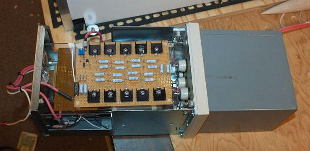
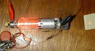
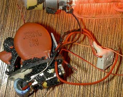
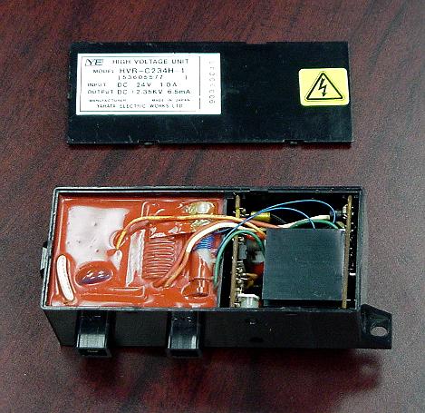
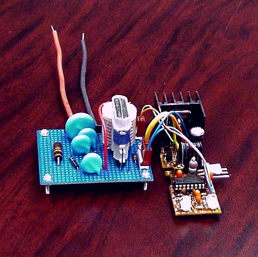
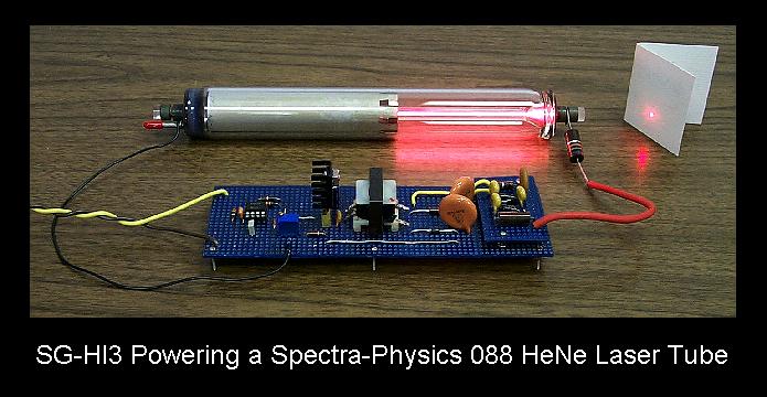