For current production lasers, the manufacturers' Web sites often provide basic specifications. For older lasers, it's often difficult to obtain detailed specs so estimates based on physical size, and then testing may be the only option.
All Melles Griot HeNe laser tubes are hard-sealed with essentially unlimited shelf life - 12 years is quoted but for all practical purposes, it is infinite. Most standard tubes have a planar HR mirror with a concave OC mirror with its curvature selected for maximum stability. This long radius hemispherical cavity configuration puts the beam waist at the HR with a slightly diverging beam from the OC. But a compensating curvature on the outer surface of the OC mirror of most laser tubes that are sold as or in standard products results in a positive lens and the beam that exits the laser is quite well collimated. (Specific applications like barcode scanning may call for a divergence other than the minimum possible to avoid the need for an additional external lens.)
And in the "I always wondered about that" department, the correct way to pronouce Melles Griot is
MEL-liss (emphasis on the first syllable).
GREE-o (emphasis on the first syllable).
This was confirmed both by someone who knew Jan Melles and Richard Griot personally, and from a VP at Melles Griot. But apparently, some of their employees don't even get it right. :)
The following data came from a variety of sources including an old Melles Griot brochure, the 1999 catalog, and the Melles Griot Web site. Go to "Product Info", "Lasers", "HeNe" or more directly to Melles Griot Lasers, "Helium-Neon (HeNe)". Then click on any location.
This is not a complete list but probably includes most of those you're likely to come across.
Red (632.8 nm):
  Minimum  e/2               c/2L      Supply    Nominal               (1)
  Output   Beam    Diver-    Mode     Opr/Strt    Tube    Tube Size   Model
  Power    Diam    gence    Spacing   (Rb=75K)   Current  Diam/Lgth  05-LHR/P-
 ------------------------------------------------------------------------------
   .4 mW  .34 mm  2.40 mR  1360 MHz  1.22/5  kV  3.2 mA   23/118 mm    007
   .5 mW  .46 mm  1.70 mR  1272 MHz  1.18/5  kV  4.5 mA   25/127 mm    640
   .5 mW  .47 mm  1.70 mR  1200 MHz  1.29/5  kV  3.3 mA   19/135 mm    002(2)
   .5 mW  .46 mm  1.77 mR  1063 MHz  1.32/5  kV  4.0 mA   25/150 mm    213
   .5 mW  .49 mm  1.70 mR  1040 MHz  1.25/5  kV  4.5 mA   29/152 mm    700
   .6 mW  .47 mm  1.70 mR  1078 MHz  1.43/5  kV  4.0 mA   25/146 mm    004
   .8 mW  .47 mm  1.70 mR  1078 MHz  1.33/5  kV  3.0 mA   25/149 mm    006
   .8 mW  .46 mm  1.77 mR  1063 MHz  1.32/5  kV  4.0 mA   25/150 mm    211
  1.0 mW  .53 mm  1.50 mR   883 MHz  1.47/8  kV  4.5 mA   29/178 mm    900
  1.0 mW  .59 mm  1.35 mR   687 MHz  1.79/8  kV  6.5 mA   37/226 mm    111
  1.0 mW  .66 mm  1.25 mR   683 MHz  1.10/8  kV  3.5 mA   28/227 mm    101

  2.0 mW  .49 mm  1.65 mR   638 MHz  1.45/10 kV  3.7 mA   29/243 mm    038
  2.0 mW  .59 mm  1.35 mR   687 MHz  1.79/10 kV  6.5 mA   37/228 mm    121
  2.0 mW  .63 mm  1.40 mR   641 MHz  1.82/10 kV  4.5 mA   29/241 mm    088
  2.0 mW  .72 mm  1.10 mR   612 MHz  1.85/10 kV  6.5 mA   29/255 mm    080
  2.0 mW  .76 mm  1.06 mR   636 MHz  1.71/10 kV  5.0 mA   30/250 mm    073
  2.0 mW  .79 mm  1.00 mR   574 MHz  1.81/10 kV  6.5 mA   37/270 mm    321
  2.5 mW  .52 mm  1.53 mR   822 MHz  1.77/10 kV  4.5 mA   25/198 mm    691
  4.0 mW  .80 mm  1.00 mR   435 MHz  2.35/10 kV  6.5 mA   37/353 mm    140
  5.0 mW  .80 mm  1.00 mR   438 MHz  2.29/10 kV  6.5 mA   37/353 mm    151
  7.0 mW 1.02 mm   .79 mR   373 MHz  2.65/10 kV  6.5 mA   37/410 mm    171

  10 mW   .65 mm  1.24 mR   341 MHz  2.64/10 kV  6.5 mA   37/440 mm    991
  12 mW  1.20 mm  3.40 mR    NA-MM   2.09/10 kV  6.5 mA   37/350 mm    185(3)
  16 mW  1.47 mm  1.40 mR    NA-MM   2.48/10 kV  7.0 mA   37/464 mm    981(3)
  17 mW   .96 mm   .83 mR   267 MHz  3.70/12 kV  7.0 mA   37/600 mm    925
  25 mW  1.23 mm   .66 mR   165 MHz  5.10/15 kV  8.0 mA   42/930 mm    827
  25 mW  1.42 mm  2.40 mR    NA-MM   3.20/10 kV  7.0 mA   42/590 mm    831
  35 mW  1.23 mm   .66 mR   165 MHz  5.10/15 kV  8.0 mA   42/930 mm    927
  35 mW  1.23 mm   .66 mR   165 MHz  5.10/15 kV  8.0 mA   42/930 mm    928(4)
Notes:
LHR models are random polarized; LHP models are linearly polarized. Not all model numbers have both versions. Barcode scanning tubes are nearly all only available random polarized.
The operating voltage across the tube itself can be found by subtracting the voltage drop across the ballast resistor (I*Rb), from the value listed in the table. Actual starting voltages are typically 3 to 5 times the tube operating voltage (though the specifications may be higher). Note that I've assumed a 75K ballast resistance for all tubes. The actual manufacturer recomendation may differ slightly but 75K should be acceptable for most.
Both random (LHR) and linearly polarized (LHP) models are available for most of the lasers listed above. The only other difference in specifications for red HeNe lasers between these is their price - about 10 to 15 percent higher for a complete polarized laser. So you can imagine the difference in the tube cost alone since everything else is identical. (The output power of "other-color" linearly polarized HeNe lasers compared to similar size random polarized models, particularly for yellow and green which have very low gain, tends to be much less since the losses through the internal Brewster plate become more significant.)
And speaking of prices, if you have to ask, you can't afford a new HeNe laser! But since you asked, prices (Summer 2002) from Melles Griot vary from around $300 for a 0.5 mW laser head to over $4,000 for one rated at 35 mW (power supply sold separately)! Prices in Summer 2005 haven't changed that much but only complete systems can be ordered on-line. Prices: $587.83 (0.5 mW) to $4,532.88 (35 mW). Fortunately, surplus prices tend to be much more reasonable - typically between 5 and 20 percent of these depending on actual age and condition as well as many other factors including your luck in finding a good deal. :)
Green (543.5 nm), random polarization:
  Minimum  e/2               c/2L      Supply    Nominal
  Output   Beam    Diver-    Mode     Opr/Strt    Tube    Tube Size   Model
  Power    Diam    gence    Spacing   (Rb=75K)   Current  Diam/Lgth  05-LGR-
 -----------------------------------------------------------------------------
  .08 mW  .88 mm  2.35 mR    NA-MM    .88/8  kV  3.7 mA   25/149 mm    004
   .2 mW  .63 mm  1.26 mR   732 MHz  1.56/8  kV  4.5 mA   29/215 mm    025
   .2 mW  .75 mm   .92 mR   373 MHz  2.62/10 kV  6.5 mA   37/410 mm    171
   .3 mW  .81 mm   .99 mR   574 MHz  2.20/10 kV  6.5 mA   37/269 mm    321
   .5 mW  .80 mm  1.01 mR   438 MHz  2.39/10 kV  6.5 mA   37/351 mm    141
   .5 mW  .80 mm  1.01 mR   438 MHz  2.39/10 kV  6.5 mA   37/351 mm    151
   .5 mW 1.35 mm  1.10 mR    NA-MM   1.94/10 kV  6.5 mA   37/351 mm    252
   .8 mW  .89 mm   .92 mR   373 MHz  2.62/10 kV  6.5 mA   37/410 mm    173
  1.0 mW  1.3 mm  1.00 mR    NA-MM   1.87/10 kV  6.5 mA   37/351 mm    161
  1.0 mW  .80 mm   .86 mR   328 MHz  2.75/10 kV  6.5 mA   37/475 mm    293
  1.5 mW  .86 mm   .81 mR   328 MHz  2.75/10 kV  6.5 mA   37/475 mm    193
  2.0 mW  .86 mm   .81 mR   328 MHz  2.75/10 kV  6.5 mA   37/475 mm    393
Green (543.5 nm), linear polarization:
  Minimum  e/2               c/2L      Supply    Nominal
  Output   Beam    Diver-    Mode     Opr/Strt    Tube    Tube Size   Model
  Power    Diam    gence    Spacing   (Rb=75K)   Current  Diam/Lgth  05-LGP-
 -----------------------------------------------------------------------------
   .2 mW  .75 mm   .92 mR   373 MHz  2.62/10 kV  6.5 mA   37/410 mm    171
   .2 mW  .77 mm   .90 mR   438 MHz  2.39/10 kV  6.5 mA   37/351 mm    141
   .3 mW  .77 mm   .90 mR   438 MHz  2.39/10 kV  6.5 mA   37/351 mm    151
   .3 mW  .86 mm   .89 mR   373 MHz  2.62/10 kV  6.5 mA   37/410 mm    173
  1.0 mW  .86 mm   .81 mR   328 MHz  2.75/10 kV  6.5 mA   37/475 mm    293
Yellow (594.1 nm), random polarization:
  Minimum  e/2               c/2L      Supply    Nominal
  Output   Beam    Diver-    Mode     Opr/Strt    Tube    Tube Size   Model
  Power    Diam    gence    Spacing   (Rb=75K)   Current  Diam/Lgth  05-LYR-
 -----------------------------------------------------------------------------
  .?? mW  ??? mm  ?.?? mR    NA-MM    .??/5  kV  3.? mA   25/149 mm    006
  .35 mW  .63 mm  1.26 mR   732 MHz  1.62/8  kV  4.5 mA   29/215 mm    025
  .35 mW  .69 mm  1.09 mR   574 MHz  1.95/10 kV  6.5 mA   37/269 mm    320
  .75 mW  .80 mm  1.01 mR   438 MHz  2.43/10 kV  6.5 mA   37/351 mm    151
  1.0 mW  .75 mm   .92 mR   373 MHz  2.59/10 kV  6.5 mA   37/410 mm    171
  2.0 mW  .75 mm   .92 mR   373 MHz  2.59/10 kV  6.5 mA   37/410 mm    173
  2.0 mW  1.17 mm 1.00 mR    NA-MM   2.09/10 kV  6.5 mA   37/351 mm    161
Yellow (594.1 nm), linear polarization:
  Minimum  e/2               c/2L      Supply    Nominal
  Output   Beam    Diver-    Mode     Opr/Strt    Tube    Tube Size   Model
  Power    Diam    gence    Spacing   (Rb=75K)   Current  Diam/Lgth  05-LYP-
 -----------------------------------------------------------------------------
  1.0 mW  .75 mm   .92 mR   373 MHz  2.59/10 kV  6.5 mA   37/410 mm    173
Orange (611.9 nm), random polarization:
  Minimum  e/2               c/2L      Supply    Nominal
  Output   Beam    Diver-    Mode     Opr/Strt    Tube    Tube Size   Model
  Power    Diam    gence    Spacing   (Rb=75K)   Current  Diam/Lgth  05-LOR-
 -----------------------------------------------------------------------------
   .5 mW  .63 mm  1.26 mR   732 MHz  1.66/8  kV  4.5 mA   29/215 mm    025
  2.0 mW  .80 mm  1.01 mR   438 MHz  2.49/10 kV  6.5 mA   37/351 mm    151
  4.0 mW  1.17 mm 1.00 mR    NA-MM   2.07/10 kV  6.5 mA   37/351 mm    161
Infra-Red (1,523 nm), random polarization:
  Minimum  e/2               c/2L      Supply    Nominal
  Output   Beam    Diver-    Mode     Opr/Strt    Tube    Tube Size   Model
  Power    Diam    gence    Spacing   (Rb=75K)   Current  Diam/Lgth  05-LIR-
 -----------------------------------------------------------------------------
  0.5 mW 1.26 mm  1.59 mR   438 MHz  2.49/10 kV  6.5 mA   37/351 mm    151
  1.0 mW 1.33 mm  1.48 mR   373 MHz  2.97/10 kV  6.0 mA   37/410 mm    171
Infra-Red (1,523 nm), linear polarization:
  Minimum  e/2               c/2L      Supply    Nominal
  Output   Beam    Diver-    Mode     Opr/Strt    Tube    Tube Size   Model
  Power    Diam    gence    Spacing   (Rb=75K)   Current  Diam/Lgth  05-LIP-
 -----------------------------------------------------------------------------
  0.4 mW 1.26 mm  1.59 mR   438 MHz  2.49/10 kV  6.5 mA   37/351 mm    151
  0.8 mW 1.33 mm  1.48 mR   373 MHz  2.97/10 kV  6.0 mA   37/410 mm    171
Infra-Red (3,391 nm), random polarization:
  Minimum  e/2               c/2L      Supply    Nominal
  Output   Beam    Diver-    Mode     Opr/Strt    Tube    Tube Size   Model
  Power    Diam    gence    Spacing   (Rb=75K)   Current  Diam/Lgth  05-LFR-
 -----------------------------------------------------------------------------
  1.0 mW  .83 mm  1.60 mR   438 MHz  2.50/10 kV  6.0 mA   37/351 mm    151
Infra-Red (3,391 nm), linear polarization:
  Minimum  e/2               c/2L      Supply    Nominal
  Output   Beam    Diver-    Mode     Opr/Strt    Tube    Tube Size   Model
  Power    Diam    gence    Spacing   (Rb=75K)   Current  Diam/Lgth  05-LFP-
 -----------------------------------------------------------------------------
  1.0 mW  .83 mm  1.60 mR   438 MHz  2.50/10 kV  6.0 mA   37/351 mm    151
Note: Some of the listed values for divergence in particular appear to be questionable. For example, for the same beam diameter, diffraction limited divergence should be proportional to wavelength. The discrepency for the 3,391 nm IR tube is particularly striking. Either the divergence or beam diameter are almost certainly incorrect. It probably doesn't matter much though because the 3,391 nm model is no longer manufactured. I also suspect the output power rating for the 05-LGR-171 may be a bit higher than listed in the source for this information.
Brewster angle window HeNe tubes:
      Minimum   Supply    Supply   Nominal                      Number
      Output    Voltage   Voltage   Tube    Tube Size   Model     of
      Power    Tube Only  Rb=68K   Current  Diam/Lgth  05-LHB-  Windows
     -------------------------------------------------------------------
      1.0 mW    1,430 V   1,870 V   6.5 mA  37/222 mm    270       1
      1.0 mW    1,460 V   1,900 V   6.5 mA  37/253 mm    290       2
      3.5 mW    1,080 V   1,520 V   6.5 mA  37/265 mm    370       1
      4.0 mW    1,030 V   1,470 V   6.5 mA  37/265 mm    570       1
      ??? mW    1,??? V   1,??? V   6.5 mA  37/265 mm    580       1
      6.0 mW    1,430 V   1,870 V   6.5 mA  37/351 mm    670       1
The most common application for one-Brewster HeNe tubes was probably for particle counting since by using an external high quality HR mirror, the intracavity flux can be several watts which makes a speck of anything stand out! (Some large one-Brewster HeNe tubes can do as much as 100 W intracavity, not these!). Passing the air/gas/whatever flow through the cavity of a one-Brewster HeNe laser is similar to passing it through the output beam of a high power laser - at a fraction of the cost (and it's much safer as well since if anything macroscopic in size (like an eyeball or piece of paper) were to block the intracavity beam, lasing simply stops with no damage to vision and no risk of fire!
The LHB models all have HR mirrors that are probably optimal for 632.8 nm (red) though newer versions, at least, may be quite broadband and better than 99.9 percent from 590 to 680 nm so operation at some of the non-632.8 nm wavelengths may be possible. However, older versions may not have such nice HRs.
Other variations on these tubes are also produced (though they may be special order). I was given an 05-LGB-580 which has an HR optimized for 543.5 nm (green). With an external green HR, the behavior is very similar to the red version but with loads of circulating green photons instead of red ones. :) I was told that this tube may have been made for the sole purpose of confirming the quality of the mirrors to be used in normal internal mirror HeNe laser tubes. So, I doubt you could buy 1. Maybe 1,000, but not just 1! Applications for such a tube would be very limited due to the low gain as it stops lasing entirely in a few minutes after cleaning the optics just due to dust settling on the B-window.
The 05-LHB-370, 05-LHB-570, 05-LHB-670, and 05-LHB-580 have wide bores and generally operate with multiple transverse modes to achieve maximum intracavity power in particle counting applications. The 05-LHB-270 and 05-LHB-290 have narrow bores like most conventional HeNe tubes. (The 05-LHB-270 appears physically similar to an 05-LHR-120 except for the Brewster window at one end.) The model 05-LHB-570 is the one-Brewster HeNe tube used in the CLIMET 9048 one-Brewster laser head described in the section: A One-Brewster HeNe Laser Tube. You can't tell from the model numbers but both Melles Griot and Hughes style designs may be used. For example, the 05-LHB-570 looks like a normal Melles Griot tube but with a Brewster angle window frit sealed to the metal end-cap instead of an OC mirror. The 05-LHB-580 looks like a Hughes style tube, but with an optically contacted Brewster window instead of an OC mirror (though some Hughes style polarized HeNe tubes are just one-Brewster tubes with an OC mirror attached to a glass tube that slips over the Brewster stem and is itself glued in place). Thus, the 05-LHB-580 is actually a much higher quality (and more expensive) tube than the 05-LHB-570 but you can't tell this from the catalog listing! Here are diagrams of each type:
One possible explanation of why the Hughes style design is used for the high quality tubes with optically contacted Brewster windows is that since Hughes already produced HeNe tubes with a glass Brewster stem (as noted above), when Melles Griot took over the Hughes HeNe laser product line, making the modifications for the graded seal to accommodate the fused silica Brewster stem (needed to match the expansion coefficient of the fused silica window) was probably easier than starting with a metal end-cap.
Zero degree AR coated window HeNe tubes:
      Minimum   Supply    Supply   Nominal                      Number
      Output    Voltage   Voltage   Tube    Tube Size   Model     of
      Power    Tube Only  Rb=68K   Current  Diam/Lgth  05-WHR-  Windows
     -------------------------------------------------------------------
      4.0 mW    1,030 V   1,470 V   6.5 mA  37/269 mm    570       1
      6.0 mW    1,670 V   2,110 V   6.5 mA  37/351 mm    252       2
      8.0 mW    1,670 V   2,110 V   6.5 mA  37/351 mm    183       1
Rather than mirrors, one or both ends of these HeNe tubes have optical flats with very high quality AR coatings to permit the use of external mirrors. One advantage of this arrangement is that external optics can be used to control polarization (the output beam of Brewster tubes is always linearly polarized and can't be changed).
The 05-WHR-252 and 05-WHR-183 appear to be identical except for the number of windows - and the loss of 2 mW with the two window version!
Here are the optical and stabilization specifications for the 05-STP-901 (from Melles Griot):
 Optical Specifications
----------------------------------------------
 Output Wavelength:               633 nm
 Output Power:                      1 mW
 M2:                               <1.1
 Beam Diameter (1/e2):            0.5 mm
 Far-Field Divergence (1/e2):    1.60 mrad
 Polarization:                 Linear, >1000
 Mode:                            TEM00

 Stabilization Characteristics - Frequency Stabilized Mode
-------------------------------------------------------------
 Frequency Stability (1 min/1 hr/8 hr):   +/-0.5/2.0/2.0 MHz
 Power Stability (1 min/1 hr/8 hr):       1.0% rms
 Frequency Offset:                        +/-150 MHz
 Temperature Dependence:                  0.5 MHz/°C

 Stabilization Characteristics - Intensity Stabilized Mode
--------------------------------------------------------------
 Frequency Stability (1 min/1 hr/8 hr):   +/-3.0/5.0/5.0 MHz
 Power Stability (1 min/1 hr/8 hr):       +/-0.1/0.2/0.2% rms
 Frequency Offset:                        +/-50 MHz

 Stabilization Characteristics - General
---------------------------------------------------------------
 Noise:                   0.05% rms
 Lock Temperature Range:  10 °C to 30 °C
 Time to Lock:            <30 minutes
The specifications for the SP-117A should be similar.
The unit I acquired is of relatively recent manufacture (as these things go) - 1996. The only major problem I found with it was a dead HeNe laser power supply brick - a Laser Drive unit rated 4.5 mA at 1,600 V, similar to the one in the SP-117. It appears to be a standard model except for a hand-printed label with "0.03 percent noise". So, it's either built with better filtering or is specially selected for this application from standard units. Using an external HeNe laser power supply temporarily allowed the controller to be tested. However, it appears to be much more finicky than the original SP-117 in Frequency Mode and would only stabilize with one of my SP-117-compatible laser heads. It basically ignored one that had a slightly leaky photodiode and my home-built clone, simply turning on the "Locked" LED but not actually doing anything. All three of these laser heads stabilize reliably on the much older SP-117 controller. I suspect that an adjustment of the gain of the photodiode preamps would take care of this - probably just turning it up all the way. So, perhaps I shouldn't be so hard on it. :)
Switching to Intensity Mode at first resulted in the heater simply turning on. The offset pot had to be adjusted to get the mode signals to be in the required range for the locking circuitry to operate, but then it would lock in either mode, with perhaps 30 seconds required to settle down.
Switching from Frequency to Intensity Mode or back caused the Locked LED to flash and the Locked relay to chatter for a few seconds. I'm not sure if this is normal behavior, but it doesn't seem to affect anything functionally. (The Locked relay provides a set of SPDT contacts that can be used to control auxiliary equipment, though there is no external connector for it. But a cable could be wired to the PCB pads and snaked out through the ventilation slots on the bottom of the case.)
Monitoring the heater drive signal on an oscilloscope shows how sensitive this feedback scheme really is. Even playing music at a moderate level evoked a detectable response. Tapping on the concrete floor resulted in an oscillation that took a few seconds to die out.
The electronic design of the SP-117A and 05-STP-901 clearly has it roots in that of the SP-117 (no A) but it has a completely redesigned PCB with TL084s in place of LF347s. But much of it looks like it is unchanged with updating only to incorporate the Intensity mode and modulation input. The heater drive is a crude pulse width modulator rather than linear pass transistor. Considering the care with which the PCB is laid out with separate analog and digital grounds and linear everything else, it seems strange to have this source of high level digital noise. The input is +12 VDC from a linear power supply. +9 VDC is provided by a LM317 linear regulator. A 555 timer generates the PWM clock and also the -9 VDC power via a charge pump. Timing delays are implemented using several CMOS monostables.
Also see the section: Description of the SP-117 and SP-117A Stabilized Single Frequency HeNe Laser.
For best performance, the controller should be adjusted to match a the specific laser head. There are only three pots inside, so this isn't that complex a procedure!
Adjustments for MG-05-STP-901 and SP-117A:
Pots R9 and R10 (500K ohms) set photodiode preamp gain while R13 (50K ohms) sets balance in INTENSITY mode. All measurements should be made with respect to AGnd (TP7). An oscilloscope is desirable for the INTENSITY mode adjustments but not essential.
It's possible that an earlier PCB revision of the MG-05-STP-901 or SP-117A may have different parts designations. In particular, the SP-117 - no "A" - has other part numbers but it should be obvious which pots and test points to use.
FREQUENCY mode:
The LOCKED LED should not be on at this point (even if it was before the adjustments were made). If one of the pots is fully CW but the signals can't be made equal, reduce
The system is basically working at this point but for the final adjustments, let it remain this way for at least another to give everything time to warmup fully.
INTENSITY mode:
Adjustments for SP-117:
The SP-117 only has FREQUENCY mode, which is functionally identical to FREQUENCY mode of the SP-117A. There are also 3 pots. R11 and R13 (the two 500K pots) are equivalent to R9 and R10 of the SP-117A with R12 (the 50K pot) adjusting the position on the gain curve. I do not know why a similar function to this last pot isn't included in the SP-117A. Or, perhaps it is and my schematics have errors. Errors? Nah. :)
The LOCKED LED should not be on at this point (even if it was before the adjustments were made).
The system is basically working at this point but for the final adjustments, let it remain this way for at least another hour so to give everything time to warmup fully.
An older Siemens HeNe laser catalog may be found at Vintage Lasers and Accessories.
Legend for Type: SM=Single mode, TEM00; MM=Multimode, P=Linearly polarized.
Red (632.8 nm):
                             Model Number
     Power      Type      Head          Tube
 ------------------------------------------------
     0.5 mW     SM                    LGR-7656
     0.5 mW     SM P    LGK-7650      LGR-7650
     0.5 mW     SM                    LGR-7651
     0.5 mW     SM                    LGR-7651A
     0.6 mW     SM      LGK-7655      LGR-7655
     0.75 mW    SM      LGK-7639
  0.75-1.0 mW   SM      LGK-7657
   0.8-1.4 mW   SM                    LGR-7655-N
     1.0 mW     SM      LGK-7655-S    LGR-7655-S
     1.0 mW     SM      LGK-7641-S
     1.2 mW     SM      LGK-7632      LGR-7632
     1.5 mW     SM                    LGR-7649
     2.0 mW     SM                    LGR-7621S
     2.0 mW     SM      LGK-7672
     2.0 mW     SM P    LGK-7634      LGR-7634
   2.2-3.2 mW   SM P    LGK-7634
     5.0 mW     SM      LGK-7627      LGR-7627
     5.0 mW     SM P    LGK-7628      LGR-7628
     5.0 mW     MM      LGK-7621-MM   LGR-7621-MM
     5.2 mW     SM P    LGK-7628-1    LGR-7628-1
   5.5-7.5 mW   SM P    LGK-7628-L
     7.0 mW     SM      LGK-7627-M
    10.0 mW     SM      LGK-7653-8
    10.0 mW     SM P    LGK-7654-8
    10.0 mW     MM      LGK-7627-MM   LGR-7627-MM
    12.0 mW?    SM      LGK-7638
    15.0 mW?    ?? ?    LGK-7654-15
    15.0 mW     SM      LGK-7665
    15.0 mW     SM P    LGK-7665-P
    18.0 mW     SM      LGK-7665-18
    18.0 mW     SM P    LGK-7665-P18
    20.0 mW     SM      LGK-7665-20
    20.0 mW     MM      LGK-7658-7
    25.0 mW     SM P    LGK-7626-L
    25.0 mW     SM P    LGK-7626
    25.0 mW     SM P    LGK-7676-L
    28.0 mW     SM P    LGK-7676
    30.0 mW     SM P    LGK-7626-S
    30.0 mW     SM P    LGK-7676-S
Green (543.5 nm):
                             Model Number
     Power      Type      Head          Tube
 ---------------------------------------------------
     0.5  mW    SM      LGK-7770      LGR-7770
     0.5  mW    SM P    LGK-7774
     0.5  mW    SM P    LGK-7786-P50
     0.75 mW    SM P    LGK-7786-P75
     1.0  mW    SM      LGK-7770-S
     1.0  mW    SM      LGK-7785-P100
     1.0  mW    SM P    LGK-7786-P100
     1.05 mW    SM P    LGK-7786-P
     1.2  mW    SM      LGK-7785-P120
     1.5  mW    SM      LGK-7785-P150
     1.5  mW    SM P    LGK-7786-P150
     2.0  mW    SM      LGK-7785-P200
     2.5  mW    SM      LGK-7785-P250 (on request)
Yellow (594.1 nm):
     Power      Type     Model
 -------------------------------------
     1.5  mW    SM      LGK-7511
     2.0  mW    SM      LGK-7512 P
Orange (611.9 nm):
     Power      Type     Model
 ------------------------------------
     2.0 mW     SM      LGK-7411
More complete specifications are available at the LASOS Web site.
The LGR-7638 laser tube is generally unremarkable except for the reasonably precise three-screw mirror adjuster at the cathode end. There is enough range that as long as you don't lose the beam entirely, it should be low risk to tweak mirror alignment on this laser. In all other respects, the tube looks like a stretch version of shorter Siemens/LASOS bare tubes with two spider bore supports and one square getter.
The following are based on physical measurements of an intact LGK-7638 laser head and my tests of a two samples of somewhat less than pristine samples of the LGR-7638 tube alone. Only one of these came close to new specs with a maximum output power of about 13 mW. Thus the electrical measurements are not likely to be exact, as operating voltage and optimal current may change with use.
The measurements and healthier of the tube samples were provided by Alan Scrimgeour in response to a posting on alt.lasers.
The LGK-7676 resonator consists of 4 full length 5/8 inch diameter rods joined by 10 thick plates. The tube is secured to these plates using sets of 4 screws with padded tips going in from all four sides at most locations. Some sets are adjustable for bore centering and optimizing straightness. The end-plates hold the mirror mounts. Coarse mirror adjustment is via some thinner rods attached to the ends of the main support rods, with pairs of nuts but no springs. This should permit the mirror mounts to be removed and replaced for cleaning of the optics without requiring coarse realignment. Fine mirror alignment uses Allen's head screws to press on rods which slightly warp the aluminum to which the actual mirror cell is attached. It works reasonably well with good sensitivity and repeatability except that the two adjustments at each end aren't quite independent. Note that with this scheme, walking of the mirrors requires turning the screws at the two ends in opposite directions. The fine adjustments are similar to those in the SP-907 but the coarse adjustments for that laser are three spring loaded nuts which means that removing the mirror mounts requires complete realignment (unless you are *really* good at counting turns!).
The entire resonator assembly is mounted on a thick piece of machined L-shaped aluminum fastened with screws at only two locations. However, under about half the thick plates (see above) on both sides of the "L" are adjustment screws to provide some sort of additional support.
The LGK-7676 uses a coaxial tube with about half of its bore exposed (as opposed to the side-arm tube with totally exposed bore used in Spectra-Physics lasers). While this does result in a more compact package (overall dimensions under 3"x3"x39"), there is less space for IR suppression magnets. In fact, the LGK-7676 only has two sets of magnets (in proximity to less than 25 percent of the bore) for this purpose but could definitely use more. Adding moderate strength magnets (greater than refrigerator strength but much less than rare-earth disk drive strength) almost anywhere along the bore - even outside the large gas reservoir - resulted in a noticeable increase in output power - about 1 percent for a single magnet. I would guess that with enough magnets, a 10 to 20 percent boost would be possible.
There are both anode and cathode ballast resistors of 81K and 27K, respectively. The power supply connector has 3 pins - anode, cathode, and Earth ground. But note that this pinout is not the same as on the physically similar connector on Spectra-Physics lasers. Thus, a Spectra-Physics power supply cannot be used on a Siemens/LASOS laser or vice-versa without modification or bad things will happen to the laser head and/or power supply. Check the power supply and laser head wiring to be sure they are compatible if not originally mated!
The sample I tested is an LGK-7676S with a spec'd output power of at least 30 mW. Of course, since I like to spend as little as possible to acquire these things, mine is a high mileage tube which apparently served hard duty in some sort of high speed printer since there was toner all over it. These are turning up on eBay (and possibly from surplus outfits directly), probably being replaced when their output power drops below a certain value by tiny diode lasers. :)
I was able to run it on my SP-255 exciter only by reducing the anode ballast resistor to 60K and removing the cathode ballast resistor entirely. Prior to this surgery, even with the input voltage to the SP-255 at 140 VAC (the upper limit of my Variac), it would only run for a minute or two (and only if it felt like it) and then cut out, not to restart for several minutes. With the modifications, it will now run all day at 120 VAC input, though restarting was sometimes still a bit of a problem until I added circuitry in an external pod to the SP-255 to boost its starting voltage. (Note that this may not be needed for LGK-7676, SP-907/107/127, and similar size lasers with lower mileage tubes.) See the section: Enhancements to SP-255.) The SP-207 should be able to drive this laser without problems but I don't happen to have one of those.
After bore straightening and mirror adjustments, I was able to squeeze more than 19 mW out of the laser at a somewhat reduced operating current (10 mA instead of the spec'd 11.5 +/- 0.5 mA). (I'm using the lower current only so I can look forward to increased power by a simple tweak in the future.) It would exceed 20 mW if when fully warmed up, the laser was shut off for 30 seconds and then restarted. But the output power would drop back to its previous level over the course of a minute or so once the "good" gas had time to migrate back out of the bore or something. :)
Here is a chart of some older Spectra-Physics HeNe lasers. Most of these are from a 1988 catalog (along with 1988 prices). Not all information was available, thus the "???" in places. You can go to the Spectra-Physics (now Newport) Web site for current models (which are now quite limited, possibly to the SP-117A frequency/intensity stabilized laser only). But the hobbyist and experimenter is much more likely to acquire the classic ones below (unless very well endowed!). Typical output power when new may have been 50 percent or more greater than the value listed.
Scans of original Spectra-Physics brochures and catalogs which include some of these lasers can be found at Vintage Lasers and Accessories.
                          Minimum
 Laser    Wave-  Mirrors  Output   Exciter  Original
 Model   length  Int/Ext   Power    Model    Price    Description/Comments
-------------------------------------------------------------------------------
 107    632.8 nm    E      30 mW?    207    $  ?,???  Similar to 127 (1)
 115    632.8 nm    E       5 mW?    200    $  ?,???  RF excited, 24" resntr.
 116    632.8 nm    E       5 mW?    200?   $  ?,???    "     "  tuning prism
 120    632.8 nm    E       6 mW     256    $  1,980  Small lab laser (2)
   -01  1,152 nm    E       1 mW      "     $  2,800    "         "
   -02  3,391 nm    E     1.25 mW     "     $  2,800    "         "
 122    632.8 nm    E       5 mW?    253A   $  ?,???  Short version of 124 (3)
 123    632.8 nm    E      10 mW?     I     $  ?,???  Between 120 and 124
 124B   632.8 nm    E      15 mW     255    $  4,900  Popular lab laser (3)
   -01  1,152 nm    E       2 mW      "     $  5,500    "         "
   -02  3,391 nm    E       5 mW      "     $  5,500    "         "
 125A   632.8 nm    E      50 mW     261A   $ 16,000  Huge-head >125 lbs. (4)
   -01  1,152 nm    E      10 mW      "     $ 17,500   more than 6 feet long.
   -02  3,391 nm    E      10 mW      "     $ 17,500    "         "
 127    632.8 nm    E      35 mW      I     $ ??,???  39 inch resonator (1)
 130    632.8 nm    E     0.6 mW      I     $  1,525  Self contained (5)
 130B   632.8 nm    E     1.5 mW      I     $  1,225    "         "
 130C   632.8 nm    E     1.5 mW      I     $  ?,???    "         "

 132    632.8 nm    I       2 mW      I     $    ???  Self contained (6)
 132P   632.8 nm    I     1.8 mW      I     $    ???  Self contained (6)
 132M   632.8 nm    I     3.5 mW      I     $    ???    "         "
 133    632.8 nm    I       2 mW     233    $    ???  Separate rect. head (5)
 133M   632.8 nm    I     3.5 mW     233    $    ???    "         "
 133P   632.8 nm    I     1.8 mW     233    $    ???    "         "
 134    632.8 nm    I     3-5 mW      I     $    ???  Self contained
 135    632.8 nm    I     3-5 mW     235    $    ???  Separate rect. head (5)
 136    632.8 nm    I       2 mW     236    $    ???  Cyl. head, rand. pol. (8)
 136P   632.8 nm    I       2 mW     236    $    ???  Cyl. head, lin. pol. (8)
 137    632.8 nm    I       2 mW     236    $    ???  Cyl. head, rand. pol. (8)
 137P   632.8 nm    I       2 mW     236    $    ???  Cyl. head, lin. pol. (8)
 138    632.8 nm    I       2 mW     236    $    ???  Cyl. head, rand. pol. (8)
 138P   632.8 nm    I       2 mW     236    $    ???  Cyl. head, lin. pol. (8)
 142    632.8 nm    I       4 mW     248    $    ???  Separate rect. head (5)
 143    632.8 nm    I       5 mW?    ???    $    ???
 145    632.8 nm    I       4 mW?    248    $    ???
 147    632.8 nm    I       8 mW     247?   $    ???  Separate cyl. head
 155    632.8 nm    I     0.5 mW      I     $    310  Educational laser (6)
 156    632.8 nm    I     ??? mW      I     $    ???    "        "
 157    632.8 nm    I       3 mW      I     $    525  Self contained
 159    632.8 nm    I       5 mW      I     $    630    "        "

 102R   632.8 nm    I       2 mW     212    $    610  Cyl. head, rand. pol.
 102P   632.8 nm    I     1.5 mW      "     $    ???  Cyl. head, lin. pol.
 105R   632.8 nm    I       5 mW     215    $    ???  Cyl. head, rand. pol.
 105P   632.8 nm    I       5 mW      "     $    ???  Cyl. head, lin. pol.

 117A   632.8 nm    I       1 mW     217A   $  3,500  Stabilized (7)
 118A   632.8 nm    I       1 mW     218A   $  ?,???    "    "    "
 119    632.8 nm    I     0.2 mW     259    $  5,775    "    "    "
Notes:
For more details on the popular large-frame Spectra-Physics HeNe lasers, see the next section.
It should be possible to possible to obtain orange (611.9 nm), yellow (593.9 nm), and green (543.5 nm) output with similar modifications (at least for the longer lasers), though the gain of these lines is only a fraction of that for the red or IR lines (1152.3 nm and 3391.3 nm) so output power will be lower.
Some photos of these lasers can be found in the Laser Equipment Gallery under "Spectra-Physics Helium-Neon Lasers". Old brochures can be found at Vintage Lasers and Accessories.
 Spectra-Physics Laser:   SP-120 (1)     SP-124B (2)            SP-125A
-------------------------------------------------------------------------------
 OUTPUT
   Wavelength (nm):          632.8   632.8 1152.3 3391.3   632.8 1152.3 3391.3
   Minimum Power (mW):        5.0     15     2.5   5.0      50     10     10

  BEAM CHARACTERISTICS
    Beam Diameter (mm):       .65     1.1   1.4    2.5      1.8   2.4    4.1
    Beam divergence (mR):     1.7     .75   1.0    1.8       .6    .8    1.4

  RESONATOR CHARACTERISTICS
    Transverse Mode:                              TEM00
    Degree of Polarization:                      1000:1
    Angle of Polarization:   Vertical (+/-5 Degrees except SP-120, +/-20 Deg.)
    Resonator Configuration:                  Long Radius
    Resonator Length (cm):     39         70.1                   177.0
    Longitudinal
         Mode Spacing:      385 MHz     214 MHz                  85 MHz

  PLASMA TUBE
    Plasma Excitation:   +3.7 kV, 6 mA +5 kV, 11 mA     -6 kV at 30 to 35 mA
                                                      (RF Opt: 15 W at 46 MHz)

    Starting Method:         ~8 kV         ~12 kV    Trigger pulse on isolated
                            (Direct from Exciter)      bar adjacent to tube.

  AMPLITUDE STABILITY
    Beam Amplitude Noise:   <.3% RMS      <.3% RMS         <2% RMS (RF: <.5%)
    Beam Amplitude Ripple:  <.5% RMS      <.2% RMS        <.5% RMS (RF: <.6%)
    Long Term Power Drift:              <5% over 8 hours and 10 °C
    Warmup Time:           30 Minutes    30 Minutes             1 Hour

  ENVIRONMENTAL CAPABILITY
    Operating Temperature:                      10 to 40 °C
    Operating Altitude:            Sea Level to 3,000 m (10,000 ft.)
    Operating Humidity:                       Below Dew Point

  POWER REQUIREMENTS
    Power Supply:                    115/230 VAC, 50/60 Hz, +/-10%
    Exciter Model (DC):   SP-256 (1)      SP-255 (2)            SP-261A
    Input Power:            50 W           125 W                 456 W

  PHYSICAL CHARACTERISTICS
    Laser Head Size:      3.26" (W) x    3.26" (W) x            ??? (W) x
                          3.66" (H) x    3.66" (H) x            ??? (H) x
                         18.48" (L)     32.00" (L)              ??? (L)

    Laser Head Weight:       7.5 lb         25 lb               100 lb

    Power Supply Size:    7.25" (W) x    7.25" (W) x            13" (W) x
                          3.72" (H) x    3.72" (H) x             6" (H) x
                          9.88" (D)      9.88" (D)              18" (D)

    Power Supply Weight:     7.5 lb        7.5 lb                30 lb
Notes:
The 1974 brochure for the SP-124A lists 611.8 nm (orange) as an optional wavelength, power not specificed. The 594.1 nm (yellow, 11 mW) and 543.5 nm (green, 5 mW) wavelengths were also mentioned in a paper but although mirror sets for yellow at least were available, it's not known if they were from SP or an official SP product. The green may have required changes to gas pressure/fill ratio and operating current as well.
Actual power from these lasers may be much more than their ratings would indicate, especially when new: greater than 35 mW for the SP-124B and up to 200 mW (!!) for the SP-125A with optimal mirrors, 150 mW with a tuning prism. (However, I don't know how likely such 'hot' samples, especially of the SP-125A, really were.)
There is also a model 127 (OEM versions: SP-107 and SP-907) with the following partial specifications (632.8 nm). Beam diameter: 1.25 mm, divergence 0.66 mrad, length 38.75", height and width: about 4", power requirements: 5 kV, 11.5 mA, starting voltage: 12 kV + 6 kV pulse. This appears to be the only large-frame Spectra-Physics HeNe laser in current production. See the next section.
Mirror sets for green (543.5 nm), yellow (594.1 nm), and orange (611.9 nm) were available for the longer lasers. (The SP-120 and SP-122 may be too short for the low gain green line.) There were also tunable versions of the SP-125 and possibly others. The SP-116 was a tunable version of the RF excited SP-115. These used a Littrow prism in place of the HR mirror.
See the following sections for more information on these Spectra-Physics lasers.
Even without powering up the laser there are two things that can be inspected to get a rough idea of the tube's health (beyond the overall condition and that it isn't in a million pieces):
The actual plasma tube in these is the SP-082 with various -dash numbers after probably related to the actual output power. I believe higher -dash numbers mean a higher output power tube (at least when new). These laser heads may sometimes be listed based on the tube number but they are the same thing since you really can't buy a tube by itself unless someone was bored and decided to totally disassemble one!
The SP-107/907 resonator is over 38 inches long and of the "Stabilite" design similar to that of the SP-122 and SP-124 but the mirror mounts differ. There is an internal L-shaped structure and outer thinner metal skin. There are two versions, differing the design of their mirror mounts:
In addition to mirror alignment, there are a pair of bore centering brackets about 1/2 and 3/4 of the way relative to the cathode-end of the laser. These have an effect on both output power and beam shape. Carefully tweaking for maximum output power should done in conjunction with mirror alignment.
The bare resonators have no beam centering adjustments and I don't see any on the packaged SP-127.
The tube has a side-mounted cathode chamber like other SP lasers but it is quite oversize - about twice the typical diameter. The ballast resistors (2 at the anode-end, 1 at the cathode-end, all 27K ohms) are mounted externally in glass tubes sealed with rubber and heat-shrink tubing. The power supply connector has 3 pins - cathode, anode, and Earth ground. But note that this pinout is not the same as on the physically similar connector on Siemens/LASOS lasers. Thus, a Spectra-Physics power supply cannot be used on a Siemens/LASOS laser or vice-versa without modification or bad things will happen to the laser head and/or power supply. Check the power supply and laser head wiring to be sure they are compatible if not originally mated!
IR suppression magnets are placed at every available location on two sides of the bore. Thin rubber boots seal the space between the Brewster windows and mirrors but these can be pushed back to permit cleaning of the windows and mirrors in-place (barely and not recommended unless the resonator has been previously disassembled as the optics stay quite clean). Some of these lasers include a metal cover and electrical heaters to decrease the warmup time required to achieve rated power and stability. CAUTION: The part of the rubber boots surrounding the tube are easily torn if the boots are removed since they tend to stick to the tube.
Depending on specific model, the SP-107/127/907 has a minimum output power of 25 or 35 mW but may do much more when new. The following is from a Spectra-Physics datasheet. Only the specs for the red version are shown but any of the other HeNe lasing wavelengths (except possibly 3.391 nm which may require a wider bore tube and removal of the IR suppression magnets) should be possible by substituting appropriate optics. A yellow or green version would be nice. :)
 Spectra-Physics Laser:        SP-107B
-----------------------------------------------------------------
  OUTPUT
    Wavelength (nm):           632.8
    Minimum Power (mW):        25 or 35

  BEAM CHARACTERISTICS
    Beam Diameter (mm):        1.25
    Beam divergence (mR):      0.66

  RESONATOR CHARACTERISTICS
    Transverse Mode:           TEM00
    Degree of Polarization:    500:1
    Angle of Polarization:     Horizontal (+/-5 Degrees)
    Resonator Configuration:   Long Radius
    Beam Waist Location:       Outer surface of output mirror
    Resonator Length (cm):     95
    Longitudinal Mode Spacing: 161 MHz

 PLASMA TUBE
    Type:                      Hard-seal (later versions), cathode in side-arm
    Operating Voltage:         5 (+/- 0.4) kV, 11.5 (+/- 0.5) mA
    Starting Voltage:          ~15 kV
    Lifetime:                  Greater than 20,000 hours

  AMPLITUDE STABILITY
    Beam Amplitude Noise:      <1% RMS
    Beam Amplitude Ripple:     <1% RMS
    Warmup Time:               20 Minutes (95% power)

  ENVIRONMENTAL CAPABILITY
    Operating Temperature:     10 to 50 °C
    Operating Humidity:        5-90% non-condensing

  POWER REQUIREMENTS
    Power Supply:              SP-207A (110/220 VAC +/- 10%)
                               SP-207A-1 (100/200 VAC +/- 10%)
                               SP-207B (90-130 VAC or 180-260 VAC)

  PHYSICAL CHARACTERISTICS
    Laser Head Size:           3.7" (W) x 3.7" (H) x 38.75" (L)
    Laser Head Weight:         23 lb
    Power Supply Size:         2.4" (W) x 1.4" (H) x 10" (L)
    Power Supply Weight:       3 lb
It is possible to run these lasers on the smaller linear SP-255 exciter but starting may be erratic or not work at all (at least for non-pristine tubes) unless the AC line voltage is increased to 125 VAC for starting (it can then be backed off somewhat while operating). A bleeder resistor of 200M ohms or so rated for 15 kV can be installed to discharge the power supply capacitors after shutdown as starting of the longer SP-107/127/907 tube apparently requires the voltage to rise from close to 0 V to start reliably on the SP-255's whimpy starter. An alternative and better solution is to add a passive boost circuit to the starting multiplier of the SP-255. This can be in an external pod requiring no modifications to the exciter itself. Note that the added starting voltage may not be needed for LGK-7676, SP-907/107/127, and similar size lasers with lower mileage tubes. If your laser starts reliably, don't worry about it. Otherwise, see the section: Enhancements to SP-255.) Make sure the laser head frame is securely connected to the power supply (and earth) ground. Since the operating voltage and current are well within the capabilities of the SP-255, the laser and power supply should both be happy once started (though the AC line voltage may still need to be slightly above 115 VAC to minimize drop out/restarts if there are line dips, expecially for a high mileage tube which may have increased operating voltage). Changing the jumpers to use one of the lower line voltage taps on the SP-255's power transformer would probably help in a marginal case (low line voltage, or a laser with a higher HeNe tube voltage or higher ballast resistance) where regulation can't be maintained with adequate current without using a Variac to boost line voltage.
The laser tube is about 20 inches long with separate bore and gas chambers side-by-side. The bore uses rather thin glass tubing and is a very large diameter for a HeNe laser - about 3 to 4 mm ID - consistent with early HeNe laser technology. The laser head is nicely mounted with lots of fine machined hardware. It has no IR suppression magnets. There are two RF connectors on the side for the Spectra-Physics model 200 RF-type power supply. One of the connectors is for the actual RF signal; the other is for starting. There is an impedance matching network located under the "tube deck". This consists of a series LC circuit (C is adjustable for peaking the tuning) between the RF input and case with the output taken from the junction of the L and C. The RF drives a dozen or so electrodes with alternating polarities in close proximity to the tube bore. The start connection goes to the input of a potted transformer which produces a several kV pulse when the "Start button" on the exciter is pressed. The starting pulse goes to a separate small electrode clamped near the center of the tube bore.
The laser has external adjustable mirrors mounted on the very solid precision milled black anodized aluminum box support structure. Both mirrors have screw adjustments for coarse alignment not accessible from outside the case without removing the end-plates. The front mirror also has external fine adjustments in X and Y via two precision Lufkin micrometers and the rear mirror is mounted on a precision slide with an external micrometer adjustment for mirror separation (try to find that on any modern laser!). I don't know if the intent of this axial adjustment (over 1/2" of travel) was to fine tune the longitudinal or transverse modes or both. Since the resonator frame would experience little if any heating (and expansion), the micrometer could be used to center a longitudinal mode and maximize output for this low gain laser. In addition, the larger movement could possibly be used to select a particular transverse mode pattern, though actually achieving TEM00 operation in such a wide bore laser might not be possible.
The power supply for the SP-115 is a high quality 15 to 25 watt 40.68 MHz RF source consisting of a crystal controlled oscillator and a power amplifier using a 4x150 tube. All active elements are tubes, of course, but out of character for the era, the oscillator and driver are built on a printed circuit board. Overall, the system looks like something straight out of the ARRL Handbook (which is probably where the design came from!).
Not surprisingly, on the sample I have, the tube has leaked and only produces a weak purple glow when the RF is turned on. The getter has the "white cloud of death" syndrome and without an aluminum can cathode, there is no possibility of getter action anywhere else. (Not that a tube this far gone would have any chance of revival in any case. The tube would make an ideal candidate for refilling since the vacuum could be breeched by cutting the exhaust nipples at either end of the gas ballast without contaminating the Brewster windows.) The SP-200 does do a nice job of lighting 20 W fluorescent lamps and most likely screwing up radio reception in the neighborhood. :)
There was also a Spectra-Physics model 116 laser which appears similar but has a tuning prism to enable wavelength selection. It goes without saying that a working sample of an SP-116 would be a real prize. :)
This system is still in production and has a sticker price of just under $5,000. It consists of a cylindrical laser head and power supply/controller. Go to Spectra-Physics/Newport and search for "117A".
The 05-STP-901 from Melles Griot appears to be the same system as the SP-117A except for the front panel decor and color scheme as it has the same specifications, controls, indicators, and connectors - including the strange three-pin Spectra-Physics HV connector not found on any other Melles Griot lasers. In fact, the PCB inside the 05-STP-901 case has the Spectra-Physics logo on it and "Fab" and "Assy" numbers that begin with "117"! As if this is not enough, the 640 MHz mode spacing of the 05-STP-901 listed in the Melles Griot catalog is the same as the Spectra-Physics 088-2 HeNe laser tube used in the SP-117. And, Melles Griot *does* have an 05-LHR-088 tube which matches the 088 physically and has a mode spacing of 641 MHz. Coincidence? I don't think so. :) Thus, a new SP-117A would probably have a Melles Griot tube inside since Spectra-Physics appears to be out of the HeNe laser business. And, a new 05-STP-901 would probably be the same except for appearance. See the section: Melles Griot Stabilized HeNe Lasers.
A search of the Spectra-Physics Web site used to return a link to a model 117 with some confusing text about the model 117, 117A, and 117B, but that 117 isn't the same as the original SP-117 or SP-117A described below, and the page seems to have disappeared. It even mentioned Brewster windows but none of these lasers ever had Brewster windows! The SP-117B was probably an OEM version of the SP-117A, possibly superseeded by the SP-117C, covered later. There may also have been an SP-117D, similar to the SP-117/A, also for OEM applications.
The following description applies to both the SP-117 and SP-117A (and MG 05-STP-901) unless otherwise noted. The laser head I dissected was an SP-117, though I expect the newer ones to be very similar. A typical SP-117 is shown in Spectra-Physics Model 117 Stabilized HeNe Laser System. The SP-117A is in an similar package with the Frequency/Intensity mode keylock switch and Locked LED added. The PCB is a completely new layout to accomodate the added circuitry for Intensity mode but everything else is similar. Why change a good thing?
The HeNe laser head is powered from a HeNe laser power supply brick (approximately 1,700 V at 4.5 mA) via the usual strange Spectra-Physics screw-lock HV connector, with a separate cable with a DB9 connector for the photodiode signals and heater power. The only thing non-standard about the brick may be a lower p-p ripple and noise specification but there is no special external regulation of this power supply. However, for it to turn on requires that the interlock plug be present on the back of the controller, that the microswitch inside the HV connector be depressed by a plastic pin in the HV plug, and that pins 2 and 7 on the signal connector be jumpered.
The cylindrical laser head contains the tube, output optics, and beam sampling assembly. A view of the parts after disassembly is shown in Spectra-Physics Model 117 Stabilized HeNe Laser Head Components. Sampling is from the waste beam at the HR-end - simply a polarizing beamsplitter (inside the black cylinder, upper left) feeding a pair of solar cells/photodiodes (glued to the metal bracket attached to it). Since this is at the HR-end of the tube, it doesn't reduce the output power. The entire guts can be pulled out by loosening a bunch of setscrews. Disassembly to the state of affairs in the photo took about 10 minutes, all completely reversible except for cutting small blobs of black RTV silicone holding the laser tube in place in the cut out aluminum cylinder at the top of the photo..
The HeNe laser tube itself looks like it is some version of a Spectra-Physics model 88 - the same type that used to be found in barcode scanners. However, note that the version used in the SP-117/A has cathode-end output, unlike the anode-end output of the barcode scanner tube. A sample I have produces over 3 mW, so it's probably a higher power version, perhaps an 088-2. As noted, those of more recent manufacture may use the Melles Griot 05-LHR-088. I have no idea if the tube is special in any other way, like having been selected for no more than two longitudinal modes or filled with isotopically pure gases or blessed by the Laser Gods. :) There were no markings of any kind on this one and at this point, I rather think that the only special requirement is that the tube not be a "flipper" - one where the polarization state of the modes switches abruptly rather than remaining fixed. In fact, I rebuilt an SP-117 laser head with a surplus 088-2 tube and it would seem to work fine. See the section: Transplant Surgery for Two Sick Spectra-Physics Model 117 Stabilized HeNe Laser Heads.
The HeNe laser tube has the multiple layer aluminum foil covering Spectra-Physics is so fond of. There may even be more layers than normal, covering a larger portion of the tube than normal. A thin film heater (copper-colored cylinder) is wrapped much of the way around the tube on top of the aluminum foil, and glued in place. Finally, here is an application where the aluminum foil actually might make sense to distribute the heat uniformly. :) The short black cylinder on the right holds a (PBS) Polarizing BeamSplitter (with the reflected output blocked) to select one of the two orthogonally polarized modes of the laser, possibly optional since it was not present on one of the SP-117 laser heads, or an SP-117A laser head that I've seen. So, either, whoever originally had these things salvaged the PBS as the only remaining useful part before selling them, or that is an option not present on all units.
Prior to assembly at the factory, the tube must be tested to determine the best orientation for maximum signal change of the two polarized modes since there is no adjustment for this once the tube is mounted with RTV silicone. The specific orientation is determined by slight asymmetries in the tube construction - random factors like mirror coatings and alignment - but should not change with age.
After an initial warmup period where the heater is run continuously, the controller enables the feedback loop which monitors the two outputs of the beam sampler and maintains cavity length using the heater so that one of the orthogonally polarized longitudinal modes is on a slope of the gain curve (frequency stabilized) or where one mode is closer to the center of the gain curve (amplitude stabilized). Although I haven't measured it, there are probably around 75 complete mode cycles before locking.
The user controls on the SP-117A consist of a switch for power and a switch to select between frequency and amplitude stabilization. There are indicators for AC power and Stabilized. (The SP-117 is physically identical but lacks the mode select switch.) After a warmup period of about 15 to 20 minutes for the laser head to reach operating temperature, the Stabilized indicator will come on and may flash for a few seconds, and after that should remain solidly on. This really indicates only that the stabilization feedback loop is active, NOT that the laser is actually stabilized and meets specs - that may require another minute or so. For the SP-117A and MG 05-STP-901, the behavior is similar in Frequency or Intensity mode. (The SP-117 has no Intensity mode.) In fact, the way they are designed, everything is identical in both modes until the Stabilized indicator comes on, then it switches to the Intensity signal for locking. If power is cycled, the delay to Stabilized is much shorter, so no actual counter delay is involved, just some circuit watching for the mode changes to slow down below some threshold. Indeed, if the photodiodes are disconnected, Stabilized will come on in under a minute even though the modes are varying wildly. Stupid electronics. :)
The internal circuitry of the controller box is relatively simple and includes some CMOS logic including several monostables (!!) for timing the warmup period, multiple op-amps and comparators, a 555 timer, voltage regulator, and switching transistor for the heater - all standard stuff. A linear power supply feeds the HeNe laser power supply and the control electronics,
Here is the pinout of the DB9 control connector as determined by my measurements. There may be errors.
  Pins    Function        Comments
 ----------------------------------------------------------------
  1,6     Heater          ~19 ohms, 12 V source on pin 6.
  2,7     Interlock       Shorted.
  3       Ground          May not be connected on some versions.
  4,5     Photodiode 1    Anode is pin 4.
  8,9     Photodiode 2    Anode is pin 8.
If anyone has information on internal adjustments of the SP-117 controller and/or a service manual or schematics, what specifically is needed to add intensity stabilization, please contact me via the Sci.Electronics.Repair FAQ Email Links Page.
There are three sheets:
This laser seems to be interesting in another respect: While for the typical ordinary HeNe laser, the modes roughly follow the profile of the gain curve as they traverse it, with this tube, the mode on one side will tend to disappear and reappear on the other side of the gain curve relatively abruptly. I don't know whether this behavior is a peculiarity or a feature but it seems like it could be beneficial. ;-)
The laser is a single unit mounted on a solid baseplate (with exposed high voltage!). It is designed to install in a cabinet painted with the decorator colors of your choice. :) See Spectra-Physics Model 117 OEM Stabilized HeNe Laser Assembly. There was a separate box with a +/-12 VDC switchmode power supply and lighted power switch as the only user control. The SP-117C has no output polarizer so that must be supplied by the user. Its operational behavior is similar to the other SP-117s, though the warmup is faster - under 10 minutes. Locking is then abrupt with no overshoot or ringing. Locking following a power interruption of a few seconds occurs in under 1 minute. When to switch from warmup to lock mode is probably detected by a complete mode cycle taking more than around 15 seconds.
The HeNe laser tube looks like the same 088 used in the other systems. It's probably from Melles Griot by its relatively thin-walled construction. The 12 VDC input HeNe laser power supply brick is hidden underneath. The PCB generally resembles the one in the SP-117A and 05-STP-901 controllers with many of the same part numbers, though there are also many differences and it has clearly been substantially redesigned. The timing is now done using 12 bit binary counters instead of multiple monostables. The majority of the discrete resistors have been replaced with resistor packs. There is also a pair of resistor packs in sockets for reasons unknown. The input is +/-12 VDC (rather than just +12 VDC), supposedly being regulated to +/-9 VDC on-board according to the test point labeling. But the resistor that sets the voltage on the sample I have has been selected to produce +/-8 VDC instead of +/-9 VDC and that works fine. There is no 555 oscillator to generate the negative voltage of the SP-117 and SP-117A controllers, so the associated PWM clock must be produced in some other way. There are pads for four large series diodes with jumpers in their place. These would be used to reduce the DC voltage to the HeNe laser power supply if more than 12 VDC were used for the positive power supply. Small MOSFETs are used to control the Enable line of the HeNe laser power supply and the Locked signal, as well as some internal signals. And, in case you're wondering, I have absolutely no intention of reverse engineering this unit the way I did the SP-117A! But I have determined most of the external connections to the 14 pin header visible in the upper left corner of the above photo based on how it is wired and the obvious PCB traces:
Pin Function --------------------------------------------------------------------------- 1 +Va - Positive analog power, +12 to +15 VDC. 2 +Va? 3 Mode control?? Input to NOR gate, pulled high. 4 Analog Ground 5 Locked Status (+Va V: unlocked, 0 V: locked, will sink 0.6 A). 6 -Va? 7 -Va - Negative analog power, -12 to -15 VDC. 8 -Va 9 Digital Ground 10 Digital Ground 11 Digital Ground 12 Digital Ground 13 NC 14 +Vd - Digital power, +12 VDC (+15 VDC with all diodes installed).
The Locked signal originates from an IRFD210 MOSFET which can sink 0.6 A, more than enough current to drive an LED - or a bank of them. :) The +/-12 VDC for the unit I have comes from a small switchmode power supply in a separate box. The analog and digital positive voltages (+Va and +Vd) are the same. I added a Locked LED there and will install a switch if the unidentified control signal does something useful.
I am in need of a user manual for the SP-117C including info to confirm what I have on the 14 pin header is correct and to determine the function of the unidentified control signal. (Grounding it either during operation or prior to power-on has no obvious effect.) If you have any info, please contact me via the Sci.Electronics.Repair FAQ Email Links Page.
Photos of a SP-120 laser head and the SP-120 resonator and tube can be found in the Laser Equipment Gallery (version 1.85 or higher) under "Spectra-Physics Helium-Neon Lasers". One thing the photos don't show because it had probably been removed, is the "starter helper" electrode, clamped to the bore near the side-arm. This is connected to the positive (anode) supply via a 100 pF HV capacitor. So, the initial rise in voltage produces a pulse on that electrode which helps to ionize the gas. Given the whimpy starter of the SP-256, it probably is worthwhile insurance. But I can understand why it was removed - getting the tube out for replacement or Brewster window cleaning is very difficult with that assembly in place.
The complete user manual for the SP-120 laser with SP-256 exciter can be found at Lasers.757.org, Manuals. On the one sample of the SP-256 exciter that I've seen, the current was set for 7.2 mA. However, I don't know if this is the default optimum setting for the SP-120 laser or whether it had been tweaked. (The specs list 7 mA at 3.7 kV.)
There is also an SP-120S. The "S" stands for "Shutter" and indeed, these have a plastic shutter lever to block the beam. They also have really cheapo plastic end-covers which block access to the screws and thus make it impossible to do any adjustment without removing them entirely. Perhaps that's a good thing. :)
There are also IR versions indicated by additional numbers after the model: A 120-1 is 1,152 nm and a 120-2 is 1,523 nm, output power not known but probably not much. So, if you obtained an SP-120 on eBay that has a tube with a nice shiny getter and good discharge color but no beam, check the dash number! Some versions might have a black VIS-blocking filter in front of the output mirror, so that would be another clue. It's hard to pass red light through a black filter. :)
The resonator uses three-screw adjustable mirror mounts for coarse alignment (tweaking these is a true pain!). Fine alignment is done via a pair of hex screw pan/tilt adjustments at each end which actually shifts the tube X-Y position without affecting the mirror. These are accessible via a pair of holes visible once the circular bezel/optics mount is unscrewed. It is possible to replace the tube in about 5 minutes without requiring major mirror re-alignment (no need to touch the coarse adjustments, only the tube centering).
The resonator is constructed from 3 pieces of thick very nicely machined aluminum stock - an L-channel and 2 end-plates bolted together to form a very rigid structure. It is supported at only three points and essentially floats inside the outer case (the "Stabilite" name as discussed for the SP-124 laser, below) which isolates the resonator from external stress (or so it is claimed). So, the clunking you hear when changing the position of the laser head is normal.
CAUTION: Unless the tube has been removed, there should be no need to clean the optics. Since there is no way to clean the Brewster windows with the tube in place and no way to clean the mirrors without removing them, it is a royal pain to be avoided. Remove, clean, install, test and tweak, repeat until output power comes back to what it was before attempting this stunt. :)
The one I obtained also used the strange SP-253A exciter - a switchmode power supply which sends medium voltage AC to a voltage multiplier/boost module in the laser head. See the end of the next section for more on this. There is also an SP-123 which appears similar but with an internal power supply.
The SP-124 laser head is a box about 76 mm (H) x 76 mm (W) x 813 mm (L) (3" x 3" x 32"), nicely massive for its size. There are threaded beam apertures at both ends though the HR is backed by a solid aluminum plate so I don't think much light would ever get through that even if there was leakage through the mirror!
This is one of SP's "Stabilite" series lasers. This approach to frequency stabilization is based on a mounting system that employs optimally located pivots in an attempt to minimize the coupling of gravitational and vibrational torques and other distorting forces to the resonator cavity itself. In the SP-124, most of the mass of the laser head is in such an optimally mounted heavy solid frame with roughly an L cross section that runs nearly the full distance between the mirror mounts and attached to each of them at three points.
Adjustments accessible externally at each end of the laser allow the beam alignment (X and Y) to be tweaked very accurately by moving the entire optics chassis relative to the head mounting studs (which accept 6-32 screws or rubber feet). The adjustment scheme is sort of interesting (to me, at least): A V-shaped block (bolted to the rosonator and case) sits between a pair of wedges (part of the mounting stud assembly) that can be moved up and down via a pair of screws (call them A and B) and retained in position by a stiff spring. Rotating both A and B equally in the same direction moves the beam in Y; rotating A and B equally in opposite directions moves it in X. The setting may then be locked.
The external mirror HeNe tube is clamped in rubber mounts at its ends and also stabilized at the 1/3 and 2/3 (approximately) positions. Metal bellows join the tube mount brackets to the mirror mounts and, in conjunction with the rubber seals, prevent dust and dirt from getting on the inside surfaces of the mirrors and on the Brewster windows. The mirror mounts have hex head bolts for adjustments with set screws to prevent their settings from changing over time. An additional metal bellows joins the OC to the treaded output aperture.
The HeNe tube itself is a bare capillary about 7 mm OD with a 1.1 mm ID (no, I didn't measure it - just trust the specs!). The cathode, getter assembly, and HeNe gas reservoir is in a side-arm at the output-end of the laser bent to run parallel to the bore. It is about 32 mm x 178 mm (1-1/4" x 7") with the 'can' electrode nearly filling the glass envelope. The anode is (naturally) at the other end of the bore along with the three 9.8K ohm (5 W at least) ballast resistors also in a parallel side-arm inside the gas envelope as apparently is the case with other Spectra-Physics lasers of this era. Interesting, they are just ordinary Ohmite power resistors. I guess this approach does reduce problems with high voltage insulation breakdown but it would be a shame if the laser went bad because a $.50 resistor failed and could not be easily replaced! The total value of about 30K ohms would seem to be rather low but might have been selected to match the needs of the SP-253A exciter (see below) or additional external ballast resistors may be required. The SP-124B version of this laser may use a more normal 81K ballast resistance.
A series of relatively weak (e.g., refrigerator note holder strength) ceramic magnets 14 mm (W) x 22 mm (L) x 6 mm (H) (9/16" x 7/8" x 5/16") are mounted in close proximity under (15 magnets) and on one side (24 magnets) all along the length of the bore wherever they fit. (See the section: Magnets in High Power or Precision HeNe Laser Heads for an explanation of their purpose.) The approximate arrangement is shown below. I may have the poles backwards (which is of course irrelevant). A cheap pocket compass came in handy to determine the pole configuration!: The magnets were positioned with their broad faces about 2 mm from the bore.
    Magnets N_S_N_S_N_S_N_S_N_S   S_N_S_N_S_N_S_N   N_S_N_S_N_S_N_S_N
    on side |_|_|_|_|_|_|_|_|_|   |_|_|_|_|_|_|_|   |_|_|_|_|_|_|_|_|
     (24)
          -------------------------------------------------------------
   HR end ============================================================= OC end
  of bore ------------------------------------------------------------- of bore

    Magnets N_S_N S_N_S N_S N_S   S_N S_N S_N S_N     S_N S_N_S N_S_N
    below   |_|_| |_|_| |_| |_|   |_| |_| |_| |_|     |_| |_|_| |_|_|
     (15)

           N_S_N                               +-----+-----+
    Where: |_|_| = 2 adjacent ceramic magnets: |N   S|S   N|
                                               +-----+-----+
I assume that the only reason there aren't 24 magnets below the tube is that
the holes in the Stabilite frame got in the way.
Apparently, there must have been a couple of power supply options for the SP-124. Most of these lasers appear to use the Spectra-Physics Model 255 Exciter (SP-255). This is a traditional HeNe power supply providing operating and start voltage through a high voltage BNC connector. However, the laser I have apparently is supposed to use an SP-253A Exciter, a model for which no one (including Spectra-Physics) seems to have any information or even acknowledge exists though I have since found out that the SP-122 laser, a model slightly shorter than the SP-120 but built more along the lines of an SP-124, may have also used the SP-253A (possibly a slightly different version or at least different jumper options). For more information on what I have found out so far about the exciter, see the section: Spectra-Physics Model 253A Exciter (SP-253A).
Unfortunately, on the system I obtained, the boost/start module (which is what I assume was supposed to be inside the head to attach to the exciter) had been ripped out with the cable just chopped off and thus I can't even determine what was there originally. So, I removed the multiconductor cable and replaced it with a HV coax (terminated with a standard Alden connector) and wired it directly to the tube anode terminal and chassis ground (recall that the ballast resistors are inside the tube. Yes, I know, the 30K ballast resistance may be too low for use with the SP-255!)
Using my SP-255 to power the head, I get a nice pink glow in the bore (more red than orange indicating a rise in pressure from slow leakage over the years) but as expected, no coherent light. The low ballast resistance is fine as far as maintaining a stable discharge (I don't know if this would still be the case if the gas pressure in the tube were correct). Maybe someday in the far distant future after that hot place freezes over AND those pigs start flying, I will get around to regassing the tube! :)
The SP-125A tube has a common cathode in the middle of the tube with two anodes, one at each end. The dual discharges are driven from its SP-261A Exciter which provides 6 kV at up to 35 mA. The SP-250 Exciter is also compatible with this laser.
With a bit of rewiring of the laser head, one could feed the anodes separately reducing the individual current requirements so that a pair of power supplies similar to the SP-255 could be used. With this sort of scheme, it should also be possible to selectively power only one of the discharge paths for reduced beam output if desired. Yes, I know, why would you ever want *less* power? :)
Two sets of ballast resistors in the laser head totaling 87K ohms (75K+12K) provide the operating voltage to each of the anodes of the dual discharge tube. They are located between the anodes and chassis ground (The SP-261A's output is negative with respect to ground. Thus, ground is the positive supply voltage). The HeNe tube's single cathode is attached directly to the negative output of the SP-261A.
The starter operates in a manner similar to that of the method of triggering the xenon flashlamp in a typical electronic flash unit or solid state laser power supply - by pulsing an external electrode in close proximity to the HeNe tube bore. The whole tube is supported by metal rods which are insulated from the cavity structure by nylon disks. One of the rods is the trigger electrode. The starter runs off a voltage from the 75K/12K ohm taps of both ballast resistors ORed together so that it repeatedly generates a trigger pulse until BOTH discharges have been successfully initiated.
The SP-261A also has a low power RF output (this isn't the same as the RF power supply option mentioned below) which drives a pair of plates in proximity to the HeNe tube. The RF is supposed to stabilize the laser power (presumably by some sort of discharge dithering process). However, the RF apparently also results in interference with local radio stations. :(
An RF power supply option is/was also available. (Possibly some version of the SP-200 though the specs don't quite match for the one I have. See the section: Spectra-Physics Model 200 Exciter (SP-200).) This would replace theSP-261A and starter entirely by driving the tube directly with radio frequency energy - 15 W at 46 MHz. Note the greatly reduced power to the tube compared to the 150 to 210 W for the DC discharge! The drive is applied via coax from a BNC connector on the back of the laser to a resonant circuit about midway in the laser head. The two phases of the output of the resonant circuit connect to a pair of 0.1 inch diameter bars running the length of the tube about 0.6 inches from the centerline suspended from insulators.
Unfortunately, many SP-125s that appear as surplus are not good for more than long boat anchors (or as a parts unit for salvage of the optics and frame). Unless the tube has been replaced relatively recently, being soft-seal, it has likely leaked to the point at which the getter can no longer clean up the contamination. Refilling is the only option and that cost would make what you paid for the laser look like pocket change. And, refilling a HeNe tube is generally not a realistic basement activity. So, if you come across an SP-125 at a low price, unless it is guaranteed to lase, buyer beware. An SP-125 sold "as-is" almost certainly means the seller couldn't get it to work (not that everything possible wasn't tried) since they likely know it is worth 10 times as much in operating condition!
Also see the section: Spectra-Physics 120, 124, and 125 HeNe Laser Specifications and Spectra-Physics Model 261A Exciter (SP-261A).
(From: Marco Lauschmann (mla@sbk-ks.de).)
The SP125A is absolutely beautiful with much chrome and a metallic blue cover! It is nearly 2 meters long and looks like an older large-frame argon ion laser. A Spectra-Physica scientist noticed that this device will deliver twice the rated power with no problems. Others have claimed as much as 200 mW for the red (632.8 nm) model!
The tube inside the lasers in the photos is the typical small Spectra-Physics side-arm type (like those in the SP-155 and other similar lasers also shown on the Web page above) but with Brewster windows instead of mirrors. However, earlier versions may look a bit different with a side-arm for the anode as well and really early versions (SP-130, no B) actually used a heated filament for the cathode (though for some reason, the schematic of the SP130 with the heated filament is dated slightly later than the schematic of the SP130B with the cold cathode design).
Based on the length of the tube, I would have expected its output power to be in the 2 to 5 mW range. However, from the specifications in the manual, it turns out to be only 0.75 mW when used with the hemispherical mirror configuration (planar and 30 cm radius of curvature), but capable of a TEM00 beam despite its wide bore (2.5 mm). With a confocal configuration using a pair of 30 cm mirrors, the beam is multimode (non-TEM00) and output power may be as much as 1.5 mW.
When I obtained the first of these lasers (the one in the top two photos), the tube actually still lit up but there was no output beam. At first I thought it might even have a chance of working since the discharge color looked sort of reasonable, though somewhat less intense than I would have expected. Fiddling with the optics didn't yield any positive results. And then, when I wasn't looking, the discharge went out! As best I can tell, a crack must have opened somewhere in the tube and it is now at much higher pressure or up to air - bummer! I can find no visible damage or any evidence of this except that it won't start even on a much larger HeNe power supply and shows no signs of a glow from an RF source. So far, the getter hasn't changed color.
I don't think this laser was ever really alive - the tube was probably gasy or helium deficient or something but I still can't explain what happened. The only place it could have leaked that I can't see is under the anode connection which is kind of potted but there shouldn't have been any heat there to cause such a problem.
And to compound my disappointment, I dinged the OC removing the tube. Enough of it may be left to still work but the optics appear to be soft-coated as the AR coating came off totally by just barely touching it. However, that still hurts. Sometimes, you just have one of those days. :(
The laser in the third photo was DOA with an up-to-air tube, seriously damaged mirrors (coatings mostly gone), and evidence of prior dissection attempts (cut wires, etc.). The tube in that one is probably one of the earliest non-heated filament types with a small cathode and separate side-arm for the anode.
However, I have since obtained a third SP-130B which originally had a red/blue discharge. But while running for a few hours, the color gradually changed to a mostly correct white-ish red-orange. And, with an optics cleaning and alignment, this SP-130B actually lases. The output power is not up to spec - about 0.25 mW at maximum current (it's rated at 0.75 mW) - but that's still a bit amazing considering its age. See the section: Reviving a Spectra-Physics Model 130B Antique Laser for details. I've had it for over 5 years now (since 2000) and it's output hasn't changed noticeably. I run it for a few seconds almost daily just to let it know that it's loved and that seems to keep it happy.
The internal power supply accounts for much of the weight and most of the height of the box and consists of:
There is no actual starter - the open circuit voltage of the power supply is about 5,000 VDC but drops to around 1,500 VDC under load.
For more info and schematics, see the section: Spectra-Physics Model 130 HeNe Laser Power Supply (SP-130).
Now, the question becomes: Do I leave the dead ones intact as examples of antique lasers or replace their tube and optics with modern 3 mW barcode scanner tubes (about the largest that would fit height-wise, a 1 inch diameter tube) to have working lasers? I guess there's nothing special about 3 mW HeNe lasers so leaving them intact would be the best option. And, it would be a shame to only have 3 mW when the power supply is easily capable of driving at least a 5 mW tube. In order to do a test with an SP098-2 barcode scanner tube (actual output: 2.8 mW), I had to add 500K ohms of ballast resistance in addition to what is built into the power supply to get the current low enough so the adjustment would include the optimum current setting. (I can hear the antique connoisseurs breathing a collective sigh of relief!) Who knows, maybe someone will drop replacement tubes and mirrors in my lap someday! Hint, hint. :)
There is also an SP-130C laser which is virtually identical in construction and function, except for the lack of an external current adjust pot.
Photos of a typical SP-155 can be found in the Laser Equipment Gallery under "Spectra-Physics Helium-Neon Lasers".
The HeNe laser tube is the classic Spectra-Physics side-arm design but with the anode electrode mounted about halfway along the length of the bore. The same tube with the anode mounted at the end would produce around 4 to 5 mW. In fact, the Spectra-Physics 157 (3 mW) and 159 (4 mW) lasers are virtually identical except for the tube's anode location and the use of a larger power supply. (The SP-156 may be similar but I haven't seen one to confirm.)
The power supply for the SP-155 is a basic transformer/doubler/multiplier design with a single transistor current regulator. The power supply on later versions of the SP-157 and SP-159 lasers may be a potted brick instead of a discrete PCB but all of the SP-155 lasers appear to retain the older quaint power supply design. :)
Note that other manufacturers sell (or have sold) lasers identical in appearance to the SP-155. For example, there is a Uniphase model 115ASL-1 and a Liconix L-388 (even though it is made by Uniphase). However, these use a hard-seal Uniphase barcode scanner HeNe tube (similar to a model 098 with a tiny collimating lens attached to its OC to reduce divergence) rather than the fancy Spectra-Physics side-arm tube we know and love. But their power supplies are similar or identical to that used in the SP-155. (There is also a Spectra-Physics model 155ASL which is physically identical to the Uniphase and Liconix lasers except for the name on the front. I assume it has the same construction though I haven't seen the insides of one up close and personal.)
Also see the section: Spectra-Physics Model 155 HeNe Laser Power Supply (SP-155).
Except as noted, these are all cylindrical laser heads with lab-style power supplies. Note that the divergence values for multimode (non-TEM00) lasers, and even whether some are TEM00 or multimode, may not be correct due to errors in both the on-line and printed datasheets I've seen.
I have two sets of specifications here. The first were mostly from the JDSU Web site as of 2006 but a few may be from other sources:
Red (632.8 nm):
  Minimum  e/2             c/2L               Nominal   <------ Model ------->
  Output   Beam   Diver-   Mode    Operating   Tube     Laser   Power
  Power    Diam   gence   Spacing   Voltage   Current   Head    Supply  System
-------------------------------------------------------------------------------
   .5 mW  .48 mm 1.70 mR 1090 MHz   1.35 kV   4.0 mA    1108/P  1205    1308/P
   .8 mW  .48 mm 1.70 mR 1090 MHz   1.35 kV   4.0 mA    1107/P  1205    1307/P
  1.5 mW  .63 mm 1.30 mR  730 MHz   1.70 kV   4.9 mA    1101/P  1201    1301/P
  2.0 mW  .63 mm 1.30 mR  730 MHz   1.70 kV   4.9 mA    1103/P  1201    1303/P
  2.0 mW  .63 mm 1.30 mR  730 MHz   1.80 kV   6.5 mA    1122/P  1206    1322/P
  5.0 mW  .81 mm 1.00 mR  435 MHz   2.35 kV  6-6.5 mA   1125/P  1202    1325/P
  7.0 mW  .81 mm 1.00 mR  435 MHz   2.45 kV  6-6.5 mA   1137/P  1202    1337/P
  10 mW   .68 mm 1.30 mR  320 MHz   3.10 kV   6.5 mA    1135/P  1216    1335/P
  17 mW   .70 mm 1.16 mR  257 MHz   4.10 kV   6.5 mA    1144/P  1218    1344/P
  22 mW   .70 mm 1.16 mR  257 MHz   4.10 kV   6.5 mA    1145P   1218    1345P
  25 mW   .70 mm 1.16 mR  257 MHz   4.10 kV   6.5 mA    1145    1218    1345
The models 1508/P and 1507/P are self-contained "Novette" lasers that run from DC wall adapters but have identical specifications to the 1308/P and 1307/P, respectively.
Green (543.5 nm):
  Minimum  e/2             c/2L               Nominal   <------ Model ------->
  Output   Beam   Diver-   Mode    Operating   Tube     Laser   Power
  Power    Diam   gence   Spacing   Voltage   Current   Head    Supply  System
-------------------------------------------------------------------------------
  .25 mW  .70 mm  .98 mR  441 MHz   2.25 kV   5.5 mA    1652/P  1207    1352/P
  .50 mW  .70 mm  .98 mR  441 MHz   2.25 kV   5.5 mA    1653    1207    1353
  .50 mW  .80 mm  .86 mR  325 MHz   2.70 kV   5.0 mA    1673P   1208    1373P
  .75 mW  .70 mm  .98 mR  441 MHz   2.25 kV   5.5 mA    1654    1207    1354
 1.00 mW 2.50 mm ?.?? mR   NA-MM    2.25 kV   5.5 mA    1654M   1207    1354M
  .75 mW  .80 mm  .86 mR  325 MHz   2.70 kV   5.0 mA    1674P   1208    1374P
 1.00 mW  .80 mm  .86 mR  325 MHz   2.70 kV   5.0 mA    1675    1208    1375
 1.50 mW  .80 mm  .86 mR  325 MHz   2.70 kV   5.0 mA    1676    1208    1376
 1.60 mW 2.70 mm ?.?? mR  325 MHz   2.70 kV   5.0 mA    1676M   1208    1376M
Yellow (594.1 nm):
  Minimum  e/2             c/2L               Nominal   <------ Model ------->
  Output   Beam   Diver-   Mode    Operating   Tube     Laser   Power
  Power    Diam   gence   Spacing   Voltage   Current   Head    Supply  System
-------------------------------------------------------------------------------
 1.00 mW  .73 mm 1.00 mR   ?? MHz   2.25 kV   5.5 mA    1677    1207    1377
 1.50 mW 2.50 mm 1.00 mR   NA-MM    2.25 kV   5.5 mA    1678    1207    1378
Orange (611.9 nm):
  Minimum  e/2             c/2L               Nominal   <------ Model ------->
  Output   Beam   Diver-   Mode    Operating   Tube     Laser   Power
  Power    Diam   gence   Spacing   Voltage   Current   Head    Supply  System
-------------------------------------------------------------------------------
 3.00 mW  .74 mm 1.10 mR   ?? MHz   2.25 kV   5.5 mA    1679    1207    1379
The "M" versions for the above lasers are apparently multimode but with incomplete specifications. (The "M" here is apparently not the same as for the ones listed below.)
The next set is what are currently listed on the JDSU Web site (Spring, 2007). Most of the specifications are the same except for operating voltage (maybe JDSU calibrated their HV probes!) but a few models are no longer present:
Red (632.8 nm):
  Minimum  e/2             c/2L               Nominal   <------ Model ------->
  Output   Beam   Diver-   Mode    Operating   Tube     Laser   Power
  Power    Diam   gence   Spacing   Voltage   Current   Head    Supply  System
-------------------------------------------------------------------------------
   .5 mW  .48 mm 1.80 mR 1090 MHz   1.25 kV   4.0 mA    1108/P  1205    1308/P
   .8 mW  .48 mm 1.70 mR 1090 MHz   1.35 kV   4.0 mA    1107/P  1205    1307/P
  1.5 mW  .63 mm 1.30 mR  730 MHz   1.70 kV   4.9 mA    1101/P  1201    1301/P
  2.0 mW  .63 mm 1.30 mR  730 MHz   1.70 kV   4.9 mA    1103/P  1201    1303/P
  2.0 mW  .63 mm 1.30 mR  730 MHz   1.80 kV   6.5 mA    1122/P  1206    1322/P
  5.0 mW  .81 mm 1.00 mR  435 MHz   2.30 kV   6.0 mA    1125/P  1202    1325/P
  7.0 mW  .81 mm 1.00 mR  435 MHz   2.45 kV   6.0 mA    1137/P  1202    1337/P
  10 mW   .68 mm 1.30 mR  320 MHz   3.10 kV   6.5 mA    1135/P  1216    1335/P
  17 mW   .70 mm 1.15 mR  257 MHz   3.80 kV   6.5 mA    1144/P  1218    1344/P
  22 mW   .70 mm 1.15 mR  257 MHz   3.80 kV   6.5 mA    1145P   1218    1345P
  25 mW   .70 mm 1.15 mR  257 MHz   3.80 kV   6.5 mA    1145    1218    1345
The models 1508/P and 1507/P are self-contained "Novette" lasers that run from DC wall adapters but have identical specifications to the 1308/P and 1307/P, respectively.
Green (543.5 nm):
  Minimum  e/2             c/2L               Nominal   <------ Model ------->
  Output   Beam   Diver-   Mode    Operating   Tube     Laser   Power
  Power    Diam   gence   Spacing   Voltage   Current   Head    Supply  System
-------------------------------------------------------------------------------
  .25 mW  .70 mm  .98 mR  441 MHz   2.25 kV   5.5 mA    1652/P  1207    1352/P
  .50 mW  .70 mm  .98 mR  441 MHz   2.25 kV   5.5 mA    1653    1207    1353
  .50 mW  .80 mm  .86 mR  325 MHz   2.70 kV   5.0 mA    1673P   1208    1373P
  .75 mW  .70 mm  .98 mR  441 MHz   2.25 kV   5.5 mA    1654    1207    1354
  .75 mW  .80 mm  .86 mR  325 MHz   2.70 kV   5.0 mA    1674P   1208    1374P
Yellow (594.1 nm):
  Minimum  e/2             c/2L               Nominal   <------ Model ------->
  Output   Beam   Diver-   Mode    Operating   Tube     Laser   Power
  Power    Diam   gence   Spacing   Voltage   Current   Head    Supply  System
-------------------------------------------------------------------------------
 1.00 mW  .73 mm 1.00 mR   ?? MHz   2.25 kV   5.5 mA    1677    1207    1377
Orange (611.9 nm):
  Minimum  e/2             c/2L               Nominal   <------ Model ------->
  Output   Beam   Diver-   Mode    Operating   Tube     Laser   Power
  Power    Diam   gence   Spacing   Voltage   Current   Head    Supply  System
-------------------------------------------------------------------------------
 3.00 mW  .74 mm 1.10 mR   ?? MHz   2.25 kV   5.5 mA    1679    1207    1379
Some of these laser heads have an "M" version (or only come in an "M" version) which have 2 inch diameter mounting rings permanently attached.
Here are some specifications for two REO tunable lasers. Both of these models were listed in their 1992 catalog though only the LSTP-1010 shows up in a recent listing and on the REO Laser Products Page. As expected, both are linearly polarized (500:1) since they use a Littrow tuning prism external to the laser tube:
Note the line at 604.6 nm (orange/yellow) which is almost never seen in other other-color HeNe lasers (at least isn't supposed to be there). :) A new LSTP-1010 with careful cleaning and alignment may actually produce more than 3 times the spec'd power for 543.5 nm, 594.1 nm, and 604.6 nm.
There was also an LSTP0050 which should have similar wavelength specs but the output powers are unknown.
And for only $4,050.00 plus shipping and handling, you can now buy your very own LSTP-1010 through Edmund Industrial Optics. :)
These lasers show up on eBay from time-to-time but are almost invariably dead or dying, though I know of one instance where such a laser turned out to work on all lines at near rated power after some tender loving care. A PMS tunable laser from 1984 is physically similar to the REO version sold today (2007). However, the Littrow prism has been improved so that installing a new tube in an old case is possible but will probably not result in quite the same performance as a new laser. The output power for all lines will not be as high as with a new prism and the green line in particular could be down right whimpy. :) Even so, the laser may still exceed the LSTP-1010 specifications (at least initially), though possibly just barely for the green line. Of course, since it's likely that the cost of a new tube is almost the same as the cost of a new laser, a tube swap is not going to be cost effective.
(From: Lynn Strickland (stricks760@earthlink.net).)
The five lines are 543.5, 594.1, 604.6, 611.9, and the common (red) 632.8 nm. You might see a flash at 629.4 nm and at 640.1 nm, but nothing to write home about. The 629 and 640 nm lines are so weak, and so close to 633 that they're sometimes hard to distinguish. There should be nothing at the IR lines (1,153, 1,523 or 3,391 nm).
As originally designed, these lasers used a Brewster window tube with a Littrow prism as the wavelength selection mechanism. The tube's internal mirror was a broad band output coupler. Don't know if it's changed, but I doubt it. (Same in 2007. --- Sam.)
The fundamental design issue is that the optimum Bore-to-Mode Ratio (BMR) for green is much higher than for red. (BMR is the ratio of limiting aperture size to mode radius. To get TEM00 operation for green, the optimal number is about 4.2, for red it's about 3.5.) If you know the wavelength, mirror curvature, and spacing, you can calculate the mode radius at any point in the cavity. The capillary bore serves as the limiting aperture, so adjusting bore length and bore diameter sets the BMR, which in turn determines transverse mode purity.
Thus, if you optimize the BMR for green power (which you have to do), the red is under-apertured, and has something like 50% off-axis modes. It's getting close to a doughnut-mode.
REO builds some of the highest 'Q' Brewster tubes in the world (probably THE highest), exclusively for the company, Particle Measuring Systems (PMS). REO and PMS used to be one in the same, but the owner sold off the particle counter biz a few years back, for something like $75 million. They now have some sort of supply agreement. The REO tubes aren't the most robust or mechanically stable, but if you get them packaged right, probably some of the highest power you can get from a given tube length. This is mostly due to coatings (all Ion Beam Sputtered), and a super-polishing process they have for substrates. As they say, it's all done with mirrors. ;)
A green Brewster tube IS a bitch! The original REO (PMS) tube was a 5 mW size - about 15" long. They did a soft-seal on the B-window; because it's fused silica. Don't know if they've gone to optical contacting/graded seal now - I'd hope so.
I think REO added a 7 mW, maybe even a 10 mW size for power. I recall seeing some longer ones at a trade show. As for cavity power, I've seen an REO B-tube with 2 HRs do almost 45 Watts of intra-cavity circulating power. They're probably higher than that now. These puppies are like $1,700 each in volume and only sold to PMS - pretty hard to come by.
(From: Sam.)
There is a weak line at 635.2 nm which could also show up as its gain is higher than that of the 594.1 nm and 604.6 nm lines. 640.1 nm is actually quite strong - next in line after 632.8 nm. See the section: Instant HeNe Laser Theory for a listing. But it's probably killed by the mirror coating selectivity.
Here is a photo of the PMS One-Brewster HeNe Laser Tube and a closeup of the Littrow Prism Tuning Assembly from PMS Tunable HeNe Laser showing its proximity to the one-Brewster tube's Brewster window. There are adjustments for wavelength and transverse (alignment). The Littrow prism is the shiny thing at the far left. The Brewster window is next to it. There is normally a tight fitting metal cover to keep out dust which has been removed to take the photo. Except for the high quality internal OC mirror and window, the HeNe tube itself isn't that much different from the common variety, though the metal envelope - typical of PMS/REO tubes - may help stability. It does have a heater coil on the OC mirror mount. According to a PMS patent (4,740,988: Laser Device Having Mirror Heating), this is to eliminate color centers that may develop in the mirror coatings from exposure to UV in the bore light. (These heaters are on some but not all PMS HeNe laser tubes.) The resistance is around 31 ohms and it runs on 9 VAC from a small transformer. The rest of this laser is unremarkable - a brick power supply and case. :)
CAUTION: The Brewster-end of the tube is all glass and fragile. The high voltage is also exposed in that area. So, if you have removed the cover of the laser, take care. It would be a darn shame if a reflex response to contact with the HV resulted in broken glass. :(
CAUTION: DO NOT attempt to remove or even loosen the screws at the bottom of the rear plate. The adjustable Littrow prism mount is directly attached to the rear plate and this is joined to the Brewster stem of the tube via an O-ring-sealed box with a removable cover. Removing the rear plate without observing exactly how this affects the relationship of the Littrow prism mount to the tube's Brewster stem and taking appropriate precautions may also break the tube.
CAUTION: DO NOT turn the micrometer adjustments further than necessary, especially in the tighten direction. I believe there should be enough clearance between the Littrow prism and Brewster window such that contact is not possible, but you really don't want to find out this isn't the case. The total useful range of the Color knob is less than 1 full turn and perhaps 1/4 turn for the Transverse knob. You won't find a blue line by turning the Color knob past green! :)
If the laser needs to be opened, take out the screws ONLY at the top at each end and lift the lid straight up. DO NOT remove or even loosen the screws at the bottom of the rear plate. Note that since the resonator is formed by all parts of the laser case, removing the lid will likely change alignment enough to matter. Thus, it is best done with the laser lasing red so adjustments can be made. Of course, if the laser doesn't work, the alignment won't matter much.
Of course, if the laser was obtained on eBay, then the non-lasing state is normal. :) :)
One problem that limits power in the REO tunable HeNe laser are losses through the Brewster window of the 1-B tube. The Brewster angle is only correct at a single wavelength so there will still be some Fresnel (reflection) at all the others. And, even super polished fused silica isn't perfect so there will still be some scatter. In addition, matching the orientation of the prism and the Brewster window of the tube is also critical to maximize power. If these issues could be eliminated, the available power at all wavelengths would increase, but this would be especially dramatic for the very weak 543.5 nm (green) and 594.1 (yellow). So, what I suggest is to place the tuning prism inside the tube envelope mounted on a two-axis bearing. Coupling through the glass can be via a pair of magnets to adjust tuning (pitch) and transverse mirror alignment (yaw). This is quite simple mechanically. Even simpler would be to attach the tuning prism assembly (also inside the tube) via a flexible metal bellows adjusted via an external mount. In either case, 2 of 3 Brewster surfaces are eliminated from the intracavity beam path. The 3rd one is for the Littrow prism which unfortunately cannot be eliminated unless a high efficiency grating could substitute for the prism. Dust collecting on the optics is also, of course, no longer a problem. :)
Red (632.8 nm):
                  Rated           Melles Griot
 Coherent Model   Power  Length   Model Number
-----------------------------------------------
  31-2017-000    0.8 mW   7.00"    05-LHR-601
  31-2009-000    0.8 mW   7.00"    05-LHP-601
  31-2033-000     2 mW   12.40"    05-LHR-321
  31-2025-000     2 mW   12.40"    05-LHP-321
  31-2058-000     4 mW   15.50"    05-LHR-151
  31-2041-000     4 mW   15.50"    05-LHP-151
  31-2074-000     7 mW   18.00"    05-LHR-171
  31-2066-000     7 mW   18.00"    05-LHP-171
  31-2090-000    10 mW   19.05"    05-LHR-991
  31-2082-000    10 mW   19.05"    05-LHP-991
  31-2108-000    17 mW   25.07"    05-LHP-925
  31-2196-000    17 mW   25.07"    05-LHR-925
  31-2140-000    35 mW   40.60"    05-LHP-928 *
* Rectangular case.
Green (543.5 nm):
                  Rated           Melles Griot
 Coherent Model   Power  Length   Model Number
-----------------------------------------------
  31-2264-000    0.3 mW  12.40"    05-LGR-321
  31-2298-000    1.0 mW  20.09"    05-LGP-293?
  31-2772-000    2.0 mW  20.09"    05-LGR-393
Yellow (594.1 nm):
                  Rated           Melles Griot
 Coherent Model   Power  Length   Model Number
-----------------------------------------------
  31-2230-000    2.0 mW  17.95"    05-LYR-173
Orange (611.9 nm):
                  Rated           Melles Griot
 Coherent Model   Power  Length   Model Number
-----------------------------------------------
  31-2207-000    2.0 mW  15.60"    05-LOR-151
I have tested three specific Coherent models:
                               Rated  CDRH    New            Melles Griot
 Coherent Model    Wavelength       Power  Power  Power   Length  Model Number
-------------------------------------------------------------------------------
  21-2090-000   632.8 nm (Red)      10 mW  30 mW   17 mW  19.05"   05-LHR-991
  31-2772-000   543.5 nm (Green)   2.0 mW   5 mW  2.7 mW  20.09"   05-LGR-393
  31-2230-000   594.1 nm (Yellow)  2.0 mW  10 mW  4.8 mW  17.95"   05-LYR-173
The "CDRH Power" is what is listed on the safety sticker. The "New Power" was the average power measured on samples of these laser heads I tested that appear to have never been used, or have seen very little use.
The HeNe laser tube is powered from a standard Laser Drive 6.5 mA, 2,100 V power supply brick via a HV BNC connector. There is no special control or regulation of this supply - it's turned on by the main power switch. But some thoughtful engineer included a high resistance bleeder to discharge the HV caps in the power supply brick after power is removed. :)
The HeNe laser tube itself is a Melles Griot (not made by Coherent!) model, labeled 05-LHR-219-158. It has similar dimemsions to an 05-LHR-120, a common 2 mW random polarized laser. But, the -158 may mean it has been specially selected to have a well behaved mode sweep cycle (not a flipper!) for this application. It may also be filled with isotopically pure gases. The tube itself puts out more than 2 mW when new, but the polarizing and beam sampling optics sucks up some of it. In addition, depending on the particular version, there is either a dielectric filter or polarizing filter in the end-cap. The dielectric filter cuts the output by about half but the this can be varied by 10 percent or so (though I'm not sure if this is intentional). The polarizing filter allows continuous adjustment of output power. (In both cases, the adjustment is done by loosening a set-screw and rotating the end-cap). According to the CDRH sticker, the output beam is supposed to be less than 1 mW. Given the wide swings in output power during warmup (see below), even with 50 percent attenuation, the peak output power may approach 1 mW.
There is a thin film heater between the tube and laser head cylinder. A pair of photosensors monitor orthogonal polarized outputs from the tube. The controller monitors the lasing modes and maintain cavity length using the heater so that a pair of orthogonally polarized longitudinal modes straddle the gain curve. The beam sensor assembly can be rotated to align the photosensors with the 2 orthogonal lasing modes as this is arbitrary from tube to tube, but probably remains fixed for the life of the tube.
The user controls consist of one (1) power switch. There are indicators for AC power and Status. After a warmup period of 20 minutes or so for the laser head to reach operating temperature, the Status indicator will change from Wait (red) to Ready (green). Doing anything that causes lock to be lost will result in a shorter delay of a couple minutes to re-establish it.
The internal circuitry of the controller box is relatively simple and includes a 741 op-amp and LM311 voltage comparator along with a TO5 power transistor to drive the heater.
Here is the pinout of the circular control connector as determined by my measurements. There may be errors.
  Pins  Wire Color  Function      Comments
 --------------------------------------------------------------------------
  1,2    Blk/Wht    Heater Pwr    ~22 ohms
  3,4    Blk/Red    Temp Sense?   ~880 ohms at 25 °C, ~1.2K when locked
  5,6    Blk/Blu    Photodiode 1  Anode is pin 5; Approximately 250 uA max
  7,8    Blk/Grn    Photodiode 2  Anode is pin 8; Approximately 50 uA max
It would appear that the difference in sensitivities is the way it's supposed to be since this was similar on 3 heads. However, the readings on an analog VOM for the photodiodes did differ on 2 heads I tested - I'm not sure what, if any significance, that has. The controller and laser head are normally a matched pair so I assume there are adjustments inside the controller to equalize the responses.
I picked up a controller and 3 laser heads in two separate eBay auctions for a grand total of $22.50 + shipping. The serial number on one of the heads matched that of the controller and while this head was initially hard to start, after running it for awhile on my HeNe laser test supply, it now starts normally.
The controller originally had a dead HeNe laser power supply brick (Laser Drive 314S-2100-6.5-2, 2100 V at 6.5 mA) which is likely the reason it was taken out of service. I replaced that with an Aerotech LSS-5(6.5) which seems to be happy enough. Using a laser power meter, one of the two modes of the laser (the one present in the output beam) could be seen cycling up and down between about 0.60 and 1.40 mW with the orientation of the beam sensor assembly adjusted for maximum peak power. Each cycle took longer and longer as the tube warmed up to operating temperature, helped along by the heater. After about 15 minutes, it would appear to try to "catch" at certain power levels but couldn't quite remain there. (This behavior may have had nothing to do with the feedback control though.) Then suddenly, after about 20 minutes, the Ready light came on and a few seconds later, it locked rock stable at 0.95 mW. :) A second laser head behaved in a similar manner but with a slightly higher final output power of 1.02 mW. No adjustments were needed inside the controller despite the fact that the second head's serial number didn't match the controller's serial number. Possibly, even better stability or slightly higher stabilized output power could be achieved with some fine tuning. (The 1.02 mW head actually had higher peak power than the 0.95 mW head. The difference is probably in part due to the photodiode sensitivities.) With the fixed filter end-caps installed, the output power dropped to around 0.50 mW. I rather suspect that these are normal power levels for this system. The third head had its cables cut but I finally scrounged a replacement control connector from a box of junk in the garage and jerry-rigged the HV BNC for testing. That laser head now works as well. It also came with an adjustable polarizer in its end-cap. With that installed on either of the other heads, the output power could be continuously adjusted from near 0 mW to about 1 mW.
Note that the Ready light comes on and then the laser locks in at the proper phase of the next mode cycle. So, basically the pea brain in the controller (no actual CPU of any kind!) decides that conditions are suitable and enables the feedback loop. It's likely based the cycle duration being longer than some magic number. :) I've also seen the ready light come on even if the laser doesn't start and when one of the previously locked heads was plugged back in after a few minutes of cooling. In the latter case, the laser was indeed locked though it might not have been able to maintain it continuously since the tube was probably no longer really warm enough.
Plot of Coherent Model 200 Stabilized HeNe Laser Head During Warmup and Plot of Coherent Model 200 Stabilized HeNe Laser Head Near End of Warmup show the output power variation due to mode cycling. Note how it seems to "snap" into regulation once the time is right. :) There are roughly 90 mode cycles during warmup prior to lock. The internal optics account for the large variation in output power. The HeNe laser tube itself has a normal mode sweep of only a few percent. If an external polarizer were added, the power might actually go to zero periodically.
Another Coherent 200 system I have has a fully functional controller but a fully dead laser head. It is very hard start, impossible to run, and way beyond end-of-life. So, that gave me an excuse to go inside.
The Coherent 200 laser head can be disassembled in a reversible manner with fewer individual parts than the Spectra-Physics 117/A or the essentially identical Melles Griot 05-STP-901. However, it doesn't come apart as easily, using a press-fit for the tube/heater sandwich.
As noted above, the tube was found to be way beyond end-of-life. If it could be convinced to start (on a lab power supply), it would not run at any reasonable current and produced no output at all. There was sputtered aluminum coating on the holes near the cathode end-cap and even through holes in the cathode can near the center of the tube. This system had obviously been left on continuously for a large number of years. It was probably not even in use for a good portion of that time, forgotten and lonely in a corner of a lab, wasting its life producing coherent stabilized photons no one was using until there were no more! :) That seems to be the destiny of so many stabilized HeNe lasers. I'll be searching for a suitable replacement tube. The original tube, a 05-LHR-219 (with or without a -158), doesn't show up in any list I've seen) but an 05-LHR-120 has nearly the same dimensions and will run on the same power supply. So, as long as one can be found that is well behaved, it will almost certainly work fine.
An operation manual and application notes for the Coherent 200 can be found at Ajax Electronics Laser/Optics Manuals under "Coherent".
(Mostly from: Skywise (into@oblivion.nothing.com).)
This is a Teletrac 1 mW stabilized HeNe laser with built in interferometer receiver. Going to Teletrac, Inc. redirects to Axsys Technologies, which only has information in their quarterly earnings reports referencing the sale of the company. But I found a user manual for a later model, but similar laser at Teletrac Stabilized Single Frequency Long HeNe Laser.
The electronics for the receiver are totally independent of the rest of the laser and are powered through the connector.
The HeNe laser tube itself has no markings. It's about 8 inches mirror to mirror. According to the user manual I found on-line it's manufactured by Zygo. Output is polarized.
The output of the OC-end goes through a collimator to get a 1 cm low divergence beam. And it is LOW divergence. I once shot this thing out my window to a brick wall about 1/4 mile away, took a walk and found the beam to have barely grown, if at all.
The HR-end has what is obviously a mode detection assembly, but it's all covered in shrink tubing.
A two terminal device (probably an LM335) is glued face down onto the glass of the tube near the cathode end for temperature sensing.
There are two low wattage filament lamps under the tube for heating.
The HeNe laser power supply is a standard brick made by Power Technology, Inc.
Temperature regulation is done by two fan blades that vibrate, driven by a piezo. The vent is on the bottom of the laser so I have to make sure the 'tail' is sticking out in free space or it overheats and the fan blades really start clattering.
From a cold start the laser reaches mode lock in about 11 minutes.
The receiver electronics are dirt simple. Just 3 good op-amps (2 LM6361N and 1 LM353). Everything else is just caps, resistors, and two trim pots. The board has space for two other 16 pin ICs but the spots are empty with no labeling to infer their function. It looks like the outputs are all analog. On the board the wires going to the detectors are labeled SIN, COS, and INT. I think the SIN and COS imply quadrature output, but have no clue what the INT is. That signal goes to the chip that got really hot. The other two signals go to the other op-amps, and I'm seeing signal there on their two test points.
Here's page with 31 photos and 1 Quicktime movie: It's under the reference section of my Lasers Page but here's a direct link: Teletrac Interferometer Laser.
(From: Sam.)
The HeNe laser tube is from Melles Griot, regardless of what the manual says. It may be a 05-LHR-120 or similar tube, possibly selected to for specific characteristics to optimize it for use in this application.
SIN and COS are likely the quadrature outputs. I'd guess INT to be "intensity" - the total output.
The LED on the back of the laser that changes from red to green as the modes cycle during warmup and then goes out when locked is a nice touch.
I'm impressed with how simple and clever this system is, though some might describe it in another way - a kludge. :-)
Red (632.8 nm):
       Output  Size
 Model Power  (LxWxH)    Applications                              Price
--------------------------------------------------------------------------
 ML800  0.8  239x72x74   Student use deomonstrations              $389.00
 ML810  0.8  239x72x74   Student use demonstrations               $399.00
 ML811  0.5  181x33x47   Pointer, CE approved                     $399.00
 ML855  5.0  540x72x74   Lecture demos, research, holography      $899.00
 ML868  0.8  328x72x74   Modulated, lecture demos, communication  $489.00
 ML869  1.5  328x72x74   Modulated, lecture demos, communication  $499.00
Green (543.5 nm):
       Output  Size
 Model Power  (LxWxH)    Applications                              Price
--------------------------------------------------------------------------
 ML815  0.08 181x33x47   CE approved   $719.00
The actual markings on a typical unit are:
  METROLOGIC INSTRUMENTS, INC.
  DAAA09-86-C-0834
  PN 11746797-2
  TUBE,LASER,PLASMA,HELIUM-NEON
  NSN 6920-01-148-4713
  WARRANTY FOR 24 MONTHS
  WARRANTY EXPIRES: FEBRUARY 1989
  SERIAL NUMBER: 703-045
There is no doubt this is a military laser. It is a machined stainless steel cylinder about 1.75 inches in diameter by 14 inches in length, with a precision welded flange at the connector-end. (See the photo on the H&R Web site.) It weighs in at over 3 pounds! The tube is potted in a rubbery material which completely fills the entire length of the cylinder with the HV connections via a pair of female contacts. There is no physical difference between the anode and cathode terminals but they are labeled "P1+" and "P2", respectively.
So, you'd think that this laser has to be at least 5 mW, right? Wrong! What's inside appears to be a 9 or 10 inch tube rated at about 1 mW with a TEM00, random polarized beam. The tube is long enough that polarization variations due to mode cycling are relatively small. The sample I have produces about 1.4 mW. It runs best on about 5 mA at 1,250 V, but remains stable down to about 2 mA. The internal ballast resistor is at least 90K ohms (might be a bit larger). So, almost any HeNe laser power supply designed for a 1 to 2 mW laser should be suitable. H&R recomends their model G7-001 but their much cheaper TM91LSR1495 works fine, and the typical barcode scanner brick would probably be adequate as well even though the current is generally lower (3 to 3.5 mA).
I don't know if the tube is simply a barcode scanner tube in a fancy expensive package, or one of Metrologic's "hard seal steel ceramic tubes" that were introduced around 1980. Those seem to have had a rather short life cycle since the higher cost might only be justified in, well, military applications. :) And, much cheaper glass tubes with frit-seals - what we know and love today - came along about the same time. By 1987, modern tube construction we well developed and soft seals had faded into history for most HeNe lasers. Someone I know tried a medical X-ray machine on the head cylinder without success. Gouging out all the potting material and ruining the magnificent packaging would hardly be justified to simply find a common barcode scanner tube inside! With the laser powered (to provide internal illumination), I tried looking in the output-end through a dielectric filter that blocked 633 nm and I think there was glass visible inside but it was hard to tell. The side of the mirror looks somewhat strange but maybe that's just because it is coated with the rubber potting compound.
On the H&R Web site, this laser is listed as a "Ruggedized HeNe Laser Head" used for some sort of weapons training/sighting application. It would also make a decent hammer. If there is a steel ceramic Metrologic tube inside, hammering nails probably wouldn't affect its lasing performance at all. I'd love to know how much one of these beauties cost the American taxpayer. :-)
The first is the HP-5501B laser head from the HP-5501A Laser Interferometry Measurement System. Position/distance resolution down to better than 10 nm (that's nanometer as in 0.000000001 meter!) were possible with this equipment. Of course, only the laser remains) but the specifications say something about the frequency stability of the laser head. (Note that the HP-5501B laser head appears to use a very different laser tube than the HP-5501A laserhead, described below.)
One other thing that is most interesting is that the original list price from the HP catalog for the laser head alone is about $9,000 (now over $12,000)!
(From: Angel Vilaseca (100604.1242@compuserve.com).)
Here is a quick description of the unit:
I have other HeNe lasers but this one really seems to be a class (or several!) above all others...
The label on the unit says:
  HENE GAS LASER, Hewlett-Packard, P.N. 05517-60501
  Date of mfg. 4-12-93, Date of instl. 4-19-93, Ser. no. 591-3
  Made in USA, Licensed by Patiex Corporation, under patent no. 4,704,583.
(From: Sam.)
The Patent is rather interesting but I'm not sure it relates directly to this laser.
There are photos of some version of the HP-5501A and HP-5501B laser heads in the Laser Equipment Gallery (Version 2.01 or higher) under "Assorted Helium-Neon Lasers". The tube used in that HP-5501A matches my strange tube but not the description above which appears to be more like the tube in the HP-5517A (though not identical). But perhaps there is at least one other type as the HP-5501B photos would seem to imply. I think this likely older 5501 tube looks much cooler than the newer HP-5517 versions. :)
The HP-5501 laser head lases in two modes that are polarized orthogonal to each other. These are split and sent down different paths. One is generally a reference and the other being the distance to be measured. The two beams rather than creating an interference pattern are beat together to and sent to a detector that outputs a difference signal. If the difference between the two beam paths changes by one wavelength of the laser (about 632.8 nm but accurate to many significant digits!), the phase of the difference signal will change by 360 degrees. The laser outputs a reference signal from beating the signals together internally. This is compared to the detector signal and an electronics package counts off the phase shifts and uses it to determine the distance traveled. The laser is supposed to have an accuracy on the order of 10 parts per billion over the life of the instrument.
(From: Wong Sy Ming (siming@singnet.com.sg).)
I picked up a HP-5517A laser head for S$50 (that's about US$30) and I have to say it's an extremely fine piece of equipment, about the same as the HP-5501B. The datasheet (which may be found by searching for "5517" on the Agilent Web Site) claims a "vacuum wavelength stability" of 0.002 ppm(!!!) over 1 hour and 0.02 ppm over it's entire 50,000 hour lifetime. Quite incredible, isn't it? It also says it has a wavelength of 632.991372 nm and a wavelength accuracy of 0.1 ppm. (that's for the "consumer grade" model, the "military calibrated" one is 0.02 ppm).
I got a rather more complete version than the one above. It came within its original casing, an inverter and a whole lot of electronics (don't know what they were for so I just took them out).
The tube is really non-standard, it has only one thick white HV wire coming out of the back and two smaller wires (red and purple, just like the HP 5501B) and the tube connects to the HV power supply through only the ONE HV cable (for the anode). I discovered later (by poking around with a separate little inverter power supply) that the not-so-obvious cathode connection is via the red wire.
The two smaller wires are connected to a "connector board" (that's what it says on the PCB) which has a big multiway connector on it, but I just ignored it and connected a 12 VDC power supply to a 470 uF or so capacitor on the board, and the tube lights up! It states a maximum power of 1 mW but the beam looks much brighter than that (probably due to the magnets along the tube which were drawing all my tools to them).
The power supply is a Laser Drive, Inc. model 111-ADJ-1, which appears to be adjustable (due to the model number and the presence of a third wire which goes to a small preset on the PCB) but I didn't fiddle with that. It only takes 0.5 A at 12 VDC which is quite incredible. CAUTION: Do NOT just connect a 12 VDC power supply to the two red and black wires from the power supply or you will get quite a nasty shock. I don't know why.
I wasn't able to trace where the two smaller wires from the tube went. The tube also has additional optics to expand the beam size to 6mm.
(From: Sam.)
The two unmarked wires and that stuff you removed were needed to actually obtain the incredible stability that HP (now Agilent) claims. I think you got a shock playing with the power supply because the HV return is via the black input wire since there is no second HV connection to the supply.
These are called "Continuous Wave Two Frequency Lasers" or more specifically: "Helium-Neon Lasers with Automatically Tuned Zeeman-Split Two-Frequency Output". They have an extremely precise wavelength of: 632.991384 nm and 0.002 ppm short term wavelength stability.
A diagram of the general approach is shown in Interferometer Using Two Frequency HeNe Laesr.
A permanent magnet does the Zeeman splitting resulting in a pair of circularly polarized outputs at two very slightly different frequencies, F1 and F2 (difference of between 1.5 and 4 MHz depending on model and specific sample). The distance between the mirrors in the HP-5517 is feedback controlled by a heating coil wrapped around the bore to force the laser tube to maintain the position of the lasing line within the doppler broadened gain curve. I assume that a wave plate somewhere in the optical path converts the circular polarized output to orthogonal polarized components which are used externally. F1 is reflected from the thing being measured or tested (e.g., disk drive servo writer) and F2 is reflected from a fixed reference. The difference frequencies (F1-F2) and (F1-F2)+dF1 are then analyzed to determine precise position, velocity, or whatever. This approach has lower noise, greater stability, and is therefore more accurate than the common single frequency interferometer. By using cavity length control to lock the difference frequency to a known reference, the actual optical wavelength/frequency can be set very accurately. Using the MHz range beat signals makes straightforward signal processing and is more immune to noise than the baseband optical signals.
There are some photos of the HP-5517 laser head as well as two versions of the HP-5501 HeNe laser (HP-5501A and HP-5501B) with descriptions) in the Laser Equipment Gallery (Version 2.01 or higher) under "Assorted Helium-Neon Lasers".
(From: Michael (phlatlyne@attbi.com).)
The HP-5501A and HP-5517A are dual frequency interferometers where the two frequencies come from the Zeeman splitting of the energy levels. The laser produces two frequencies polarized normal to each other which are beat together internally to create a reference signal (which is just the difference between the two laser frequencies and is about 1.5 to 2 Mhz for the HP-5501A and HP-5517A and a bit higher on the newer ones). The beam is then sent to a beamsplitter outside the laser which sends the vertical polarization one way and horizontal the other. One of these frequencies will be the reference beam, the other will be reflected from the object whose distance is being measured. The configuration looks a lot like a Michelson interferometer but the beam splitter is different. When the two beams are recombined and beat together, the resulting beat signal can be compared against the reference signal from the rear panel of the laser head. If you crunch through the math you will see that if the object being measured moves through a distance of one wavelength, the phase of the beat signal will move through one complete cycle (2*pi).
The naked tube is shown in HP-5501A Laser Tube Removed From Magnet and Output Optics Assembly. The normally enclosed part is really just a very think walled fine-ground bore inside an outer glass envelope. A spring (visible through the glass at the left) at the rear holds the PZT, HR mirror, bore, and OC mirror in place. No adjustment is possible. There are distinct multiple spots on the card because the output window is at a slight angle and not AR coated.
Both the HeNe laser power supply and piezo power supply run off the -15 VDC power supply. An interlock switch (easily defeated) prevents operation with the cover removed. In the HP-5500C, the HeNe laser power supply has an additional input that may be a current adjust signal, and the piezo driver power supply provides 0 to 1.5 kVDC when fed a control voltage of 0 to 15 VDC relative to the negative input. However, in the HP-5501A, the potted power supply bricks have no inputs other than power. Rather, current and voltage control are accomplished by externally regulating the input current.
The output of the laser tube is passed through a quarter wave plate to convert the circular polarization to orthogonal linear polarization components, and then through a half wave plate to rotate the linear polarization by an arbitrary, but fixed angle to line the two linearly polarized components up with subsequent optics. The beam is then expanded and collimated and passed through an angled partially reflecting plate located just beyond the collimating lens on the laser tube assembly. This deflects about 20 percent of the beam to a polarizing beamsplitter which sends each component to its own photosensor to provide the frequency control feedback. A control loop uses these signals to adjust the PZT, and thus resonator length, so that the two signals are of equal amplitude. The difference of the two signals is the frequency/phase reference.
The laser stabilization control algorithm is actually dirt simple: The voltages from the photodiodes corresponding to the two polarization components are compared in an integrator which maintains the PZT voltage at a level so they are equal. (There is an adjustment to compensate for slight differences in amplitude resulting from beamsplitter ratio and photodiode sensitivity.) While crude and simple to implement, this approach is adequate to achieve the needed stability. The electronic reference signal is derived from the slight residual difference frequency present in one of the polarization components. A loss of the reference signal or the PZT control voltage going outside its normal limits will set the "Tune Fault" flag and turn on the "Retune" LED. The HP-5501A control electronics are not smart enough to deal with a situation where the system goes way out of lock, so there is a pushbutton (and a TTL signal) to retune the laser. This clamps the PZT control voltage at its lowest value for a short time and then releases it to ramp up to the lock point. Requiring external intervention (whether manually or by computer) assures that a measurement will never be made when the laser isn't stable.
The HP-5501A laser head requires +15 VDC and -15 VDC for power. (There is also a +5 VDC pin but it is an output according to the manual.) The two voltages (and common) are all that is needed to operate the laser head but an interlock switch (on the right side at the rear of the case) must be depressed to turn on the laser tube. I haven't yet looked at the output with a photodiode or scanning Fabry-Perot interferometer but after a few seconds, the "Retune" LED goes off, similar to if the "Retune" button is pressed. And then there is a stable reference signal. I have since acquired an operation and service manual for the HP 5501A laser head which confirms the information above.
HP-5501A reference connector J1
   Pin      Function
 ---------------------------------------------
    A       Accessory +15 VDC fused
    B       +15 VDC return
    C       Reference (difference) frequency
    D       Complement of J1-C
HP-5501A power connector J2
   Pin      Function
 ---------------------------------------------
    A       +15 VDC input
    B       -15 VDC input
    C       +5 VDC output (testpoint)
    D       Power ground
HP-5501A diagnostic connector J3
   Pin  Function      I/O   Comments
 ------------------------------------------------------------------------------
    A   +15 VDC TEST   O    Sample for diagnostics
    B   -15 VDC TEST   O    Sample for diagnostics
    C   +5 VDC TEST    O    Sample for diagnostics
    D   SYS COM        -    Ground/return
    E   Retune_CMD-    I    Active low to initiate PZT tune/check cycle.
    F   Retune_Failure O    Active high output indicates failure of PZT
                             tune/check cycle.
    J   Retune_Status  O    Active high when tune/check cycle is in progress.
    K   Laser_Cur_Err  O    Active high indicates laser tube current is
                             outside acceptable limits.
    L   Error          O    Logical OR of J3-J, J3-K, and PZT voltage outside
                             of specifications.
    M   L I Mon Test   O    Laser current sample for diagnostics.
    N   PZT Mon Test   O    PZT voltage sample for diagnostics.
    P   Ref OK Status  O    Active low diagnostic signal indicates laser
                             is properly tuned.
Like the HP-5501A, the HP-5501B also requires only +/-15 VDC to power up. There is no case interlock on the laser I have, though one is shown in the manual so I assume this is either an addition or deletion depending on version. When power is applied, at first, only the +/-15 VDC power LEDs come on. After 2 or 3 minutes, the "Ready" LED begins to flash at about a 1 second rate. After another minute or so, the "Laser On" LED comes on and the beam appears. Finally, a minute or so after that, the Ready LED comes on solid and remains that way. Specific times for one test beginning from a cold start at an ambient temperature of about 65 °F were: (min:sec) 3:15, 1:35, and 0:48. The first of the times is called "preheat" and is determined by how long it takes for what HP calls the "laser rod" to reach operating temperature. The laser rod is the large glass bore of the laser tube to which the mirrors are clamped at either end. It thus controls cavity length. The temperature is sensed by disabling the heater drive and measuring the resistance of the heater coil every 25.6 seconds. The warmup is much shorter if the laser is restarted after having been running: 1:00, 1:20, and 0:50. Only after the Ready LED is on solid, do the reference signals appear. The HP-5501B adjusts the cavity length so that the two polarized components of the beam (the Zeeman split longitudinal modes) have equal power. Interestingly, there is only one photodiode sensor which is alternatively switched between beams using a liquid crystal polarization rotator. A sample-and-hold then outputs to the error amplifier of the optical mode control feedback loop.
There are two outputs of about 5 to 6 V p-p (centered about 0 V), 180 degrees out of phase. For this laser, the reference frequency is about 1.80 MHz. There is no need for a "Retune" button as with the PZT based system of the HP-5501A. Also unlike the HP-5501A, there are no other signals to or from the HP-5501B (no large connector), only the +5 VDC output on the power connector, and a fused +15 VDC output on the reference connector.
There were two problems with the particular laser I have that I had to deal with. The first is that the tube won't stay on stably at the 3.5 mA setting (fixed) of the power supply but works fine at 4 mA and still produced adequate output power. Such a condition is usually due to the tube having been run for a long time, which wouldn't be surprising with a surplus HP-5501B laser head. Since the existing power supply has no current adjustment, I needed to find a similar size HeNe laser power supply brick (1"x1.5"x4" or smaller) that will run on 15 VDC to replace it that can be set for 4 to 4.5 mA. The tube seemed healthy enough otherwise. I installed one that runs the tube at 4 mA but draws more DC input current than the original, and possibly for that reason, the controller aborts and resets after about 1 second when it turns the laser on. For now, to get around this, I have connected the HeNe laser power supply directly to the raw -15 VDC and added a transistor to drive its enable input when the original laser power turns on. That appeared to work fine. But after replacing the cover (or what of it I have - there is no front plate - which I would like to obtain), the laser tube wouldn't come on. :( I discovered that it needed the room light to start! This is a relatively rare malady for HeNe laser tubes but more common for neon lamps and glow-tube fluorescent lamp starters. So, there is now a decorative red LED shining on the back of the tube which is lit when the laser is powered. An HeNe laser power supply with a higher starting voltage would probably make this kludge, oops, feature, unnecessary. But no one will ever know about it. :)
HP-5501B reference connector J1
   Pin      Function
 ---------------------------------------------
    A       Accessory +15 VDC fused
    B       +15 VDC return
    C       Reference (difference) frequency
    D       Complement of J1-C
HP-5501B power connector J2
   Pin      Function
 ---------------------------------------------
    A       +15 VDC input
    B       -15 VDC input
    C       +5 VDC output (testpoint)
    D       Power ground
Plot of Hewlett Packard Model 5517A Stabilized Laser During Warmup shows how this laser behaves. Note that the entire warmup period from laser on to locked is only around 3.5 minutes because the heater for the active mode control is inside the laser tube wrapped directly around the bore.A laser with an external heater could take 20 minutes or more to lock. The control algorithm appears a bit more sophisticated than used on some other stabilized lasers, checking periodically for the status, and entering a "fine adjust" mode about half way through the warmup period. I believe that the changeover from coarse to fine mode is also when the READY LED starts flashing. A short while after it locks is when the READY LED comes on steady. There are around 90 complete mode cycles from a cold start to Ready on assuming the temperature is still increasing even when during the several attempts to lock.
The tube itself is similar or identical to that of the HP-5501B. However, the tube's enclosure appears to have been cost-reduced: It is a base metal casting rather than being constructed from precision machined parts. The output optics consists of a beam expander/collimator (the black and silver object just to the left of the power supply danger label) and an additional optical assembly to the left of this. Its front and rear halves contain what appear to be AR coated optical quality mica pelicles oriented at slight, but different angles. The front and rear sections can be rotated independently and they were sealed with blue paint once the perfect orientations were found.
After thinking about this, I came to the conclusion that the two mica (or whatever) pieces might act together as an adjustable waveplate where their orientations with respect to each other control the relative delay of their e and o axes, and their overall orientation determines the orientation of any linear polarization components in the output beam. (The Zeeman split beam directly out of the HeNe laser tube should be circularly polarized.) If this were set up for a 1/4 wavelength retardation, these could be used convert the circular polarization of the Zeeman split beam back into linear polarizations that could be separated out with a polarizing beamsplitter at the detectors. In fact, having acquired an operation and service manual for the HP 5501A (which functions in a similar manner), this is exactly how it works.
If two modes were oscillating simultaneously as might be the case with the reasonably short HeNe laser tube in the HP-5517, then it should be possible to recover their two polarizations and use this in the temperature control feedback loop to stabilize the difference frequency - which ultimately determines the accuracy of the interferometer measurements.
One interesting characteristic of the HP-5517 HeNe laser tube I have is that the difference frequency only appears for perhaps 10 percent of the time as it heats up - possibly only when the dominant longitudinal mode is near the center of the gain curve. I don't know if this is the normal behavior for these lasers but suspect that is is based on experiments with common barcode scanner HeNe laser tubes inside strong magnetic fields. With those as well, the beat frequency would come and go as the tube heated and expanded with this effect becoming more pronounced when the magnetic field encompassed the entire tube as it does with the HP-5517.
Experimenting with and without the presence of the mystery optics showed some effect. With them removed, there was absolutely no indication of a polarization preference in the output beam at any time. When the optics were installed and aligned to the original blue paint, the symmetry of the beat waveform, if nothing else, was polarization dependent. In addition, just after the output beat appear as well as just before it disappeared, the polarizer would suppress the beat entirely when oriented so that its axis was parallel or at 90 degrees to the axis defined by the blue paint. These perhaps weren't quite as dramatic as the effects I was hoping for but confirmed some of the speculation at least.
Scans of original product brochures for the Model 200, 220, and 260 lasers, and html versions, as well as general desciptions and a price list can be found at Vintage Lasers and Accessories Brochures under "Laboratory for Science". The brochures include a nice description of the principles of operation and applications considerations in addition to the specifications.
The following brief descriptions include extensive contributions from David Woolsey (http://www.davidwoolsey.com/).)
There were three Laboratory for Science stabilized HeNe lasers known to have been produced and sold:
All three models had the same size power supply/control box but the laser head for the Model 260 was longer than those for the models 200 and 220. The user controls and general operating procedures are also basically the same for all models.
A number of features and attention to detail set these lasers apart from most other commercial stabilized HeNe lasers that are or have been available. These are described with respect to each model in the following sections. Unfortunately, clever ideas and implementation are often not the most important factors in determining the success of a product or business.
Even with the superb technology, not many of any of these lasers were ever sold. The total production run for all the years of the product line from the early 1980s to sometime in 1995 was soemthing like: 300 for the Model 200, 60 for the Model 220, and only 10 for the Model 260. There are references to other models ranging up to 280 in the product literature, but someone who actually worked at Laser for Science throughout the years of ultra stable laser production never heard of them going beyond the discussion stage.
Ironically, the extensive discussion of retro-reflections in the product brochures may have scared off potential buyers. Nearly half the text in the brochures for the LFS-200, LFS-220, and LFS-260 is related to the effects and mitigation of retro-reflections which some people might interpret as a deficiency with these lasers. Retro-reflections are a problem with all lasers, but especially with lasers designed to have the best stability performance. Other manufacturers tend to simply mention retro-reflections in the operation manual - not the product brochures! - as something to be avoided, but even there, they don't dwell on it.
Even experienced laser jocks find it hard to understand how reflected light with a power level 1/100,000,000 or less compared to the intra-cavity power can have an effect on the behavior but it definitely can with these type of lasers.
If anyone has schematics, a service manual, or other detailed documentation for any of the Laboratory for Science lasers (or an actual Laboratory for Science laser!) stached away they no longer need, please contact me via the Sci.Electronics.Repair FAQ Email Links Page.
The LFS-200 and LFS-220 are described in the order in which I acquired samples.
Although LFS is now out of business, other companies do offer transverse Zeeman stabilized HeNe lasers. One example is NEOARK (Japan).
Among the features and attention to detail that sets the Model 220 laser apart are:
The well known commercially available HeNe lasers I'm aware of implement very few, if any of these. And note that many duel frequency Zeeman like the HP-5501A/B, HP-5517, and others, use simple dual polarization mode stabilization techniques despite their being Zeeman lasers.
Scans of an original product brochure for the LFS-220 can be found at Vintage Lasers and Accessories Brochures under "Laboratory for Science". A much more compact html versions is at Model 220 Ultra Stable Laser Brochure. The brochure includes a nice description of the principles of operation and of course, the specifications.
The first Model 220 I (Sam) acquired on eBay - serial number 51 - has IC date codes and PCB fab dates between 1981 and 1986. But if the serial numbers started at 1 (or even 10 as has been suggested) rather than 50 and only 60 lasers were ever built, it may be much newer than 1986, possibly between 1988 and 1992. So what if the chips are a bit moldy, they haven't changed in any way other than dropping in price by 1 or 2 orders of magnitude since 1981. :) Maybe LFS bought their chips from PolyPacks (a popular surplus outfit for cheap chips that also no longer exists). ;-)
While the tube in this laser is weak - around 0.8 mW on a good day which is about half the minimum power spec - this is more than adequate to provide a stable beat frequency signal. Originally, the laser was going through what appeared to be normal warmup, but would not lock after the warmup period and the Lock Level indicator came on. The Model 220 has a headphone jack to permit listening to the PLL error signal (as do the other models as well) and a knob to adjust the PLL gain. And while the knob affected the sound in the headphones, there was little correlation with anything else. It was like a bad SciFi movie sound track! I was thinking there must be electronic problems preventing a stable lock from being achieved. Fortunately, all ICs are standard 4000-series CMOS and common analog parts. Unfortunately, it's not likely that a schematic will be available given how few of these were probably built. Google gas been totally incapable of finding much of any useful information beyond the brochure for the Model 200 on David Woolsey's Web site and a few journel references citing the use of Laboratory for Science lasers for such-an-such research.
However, a miracle happened. Someone sent me the user manual for the Model 220 and lo and behold, that empty socket under the controller I had been pondering since acquiring the laser needed a jumper plug to complete the internal signal paths! It provides access to all the critical input and outputs of the internal architecture of the Model 220 controller with the intent to permit the use of an external frequency reference, remote control and monitoring, and other advanced functions. The jumper block must have either fallen out in shipping, or the previous owner had been using the remote hookup and kept the cable. No wonder it didn't work. Nothing was connected together! So there were electronic problems of sorts. :)
With the default jumper plug constructed and installed, *everything* started working in a manner that actually made sense. The Mode LED went on and off as the modes cycled in the HeNe laser tube during warmup and the headphones produced a satisfying chirp a couple times during each mode cycle. When the 30 minutes or so warmup time was completed, the laser locked instantly!
The sound from the headphones is nearly pure white noise and the beat frequency appears rock stable on an oscilloscope and around the 425.8317 kHz it should be based on the PLL synthesizer BCD switch settings of 511. (The frequency is: 3.4 MHz*m/M where M is the switch setting and m is 32, 64, or 128, preselected based on the laser tube to provide the maximum number of possible discrete Zeeman frequencies.) I intend to check it on a frequency counter but have little doubt that will also show the correct frequency with crystal accuracy. Unfortunately, I don't have a spectrum analyzer or an iodine stabilized laser to check it more precisely. The stability should increase is allowed to warm up for longer - 90 minutes is the time to reach spec'd performance. Originally, I thought it might not be working quite correctly due to the sound from the headphone jack having rumbling and other non-white noise components, but I now believe that may have been due to acoustic feedback since I was actually listening using a stereo amp.
Here are some photos:
The HeNe laser tube construction is nothing special, at least on the outside. Like the two mode stabilized HeNe lasers, a Spectra-Physics 088-2 or similar tube would work. But the actual tube used by LFS was apparently custom built though. Some, if not all, were filled with isotopically pure Ne20 or Ne22 to provide the narrowest linewidth and/or to select the precise line center, and possibly He3 as well. Later ones were made with a special bore support spider that eliminated the "slip-stick" behavior during warmup of some other designs.
The waste beam from the HR-end of the tube is used for the reference beat tone. It has a polarizing filter between the tube and the photodiode and a glued-on wedge to make sure the waste beam can't reflect back into the bore. There is an AGC circuit of sorts for the photodiode so that a usable signal can be obtained as the tube ages regardless of a (reasonable) decline in tube power.
The tube is rather elaborately suspended as can be seen in the photos. The suspension provides some degree of vibration isolation and there is even a fine thread screw (visible on the top of the laser head) to rotate the tube by a few degrees. The complex suspension was designed to minimize stress in the glass envelope and eliminate stick-slip noise due to length changes of the overall tube. It also allowed the tube to be rotated by a 100 pitch screw adjustment without twisting the tube at all. This was desirable to align the tube's birefringence axis (mode orientation) precisely with the magnetic field.
The entire laser head is thermally regulated by a temperature controller which is the circuitry on the lone PCB inside the head. The temperature set-point can be adjusted via a pot accessible from underneath the laser head. Power resistors attached to the baseplate on which the tube and magnet assembly is mounted provide the heating and an LED on the rear panel of the laser head shows the amount of power to the heater by its intensity. The baseplate bolts to the outer aluminum case with close-fitting end-plates. Although perhaps not obvious from the photos, the wall thickness is much greater than that of most other HeNe lasers.
There is also a rather elaborate transducer attached to the tube. While serving a similar function to the heaters on many mode stabilized lasers, the design was optimized for fast response. Power to this heater is what is controlled by the PLL responsible for locking the laser.
The transducer consists of a dense "zig-zag" run of copper wire about 3.5 inches long Epoxied directly to the outside of the glass tube envelope. The wire is oriented (back and forth) along the long axis of the tube, *not* as a helix or coil (it is not an inductor). When a current is run through the winding the wire heats up and immediately pulls (stretches) the glass with it. The response bandwidth is something like 10 kHz since the length change between the mirrors did not have to wait for the glass to heat up. With the wire arranged along the tube axis all of its change in length was in the intended direction - unlike with a the the more common coil arrangement.
With a simple coil, the initial change in dimension when current is applied is an increase in winding *diameter* which pulls the glass with it (expands the tube diameter) and causes an initial *shortening* of the tube. The shortening is followed by a lengthening as the heat from the transducer diffuses into the glass. This is not a good way to make a fast feedback loop. Also unlike other heater schemes generally used, with the wire directly attached to the tube glass, there is nothing in between to limit the response as with taped on thin-film heaters.
On the anode-end of the HeNe laser tube (the front of the laser head and output) is a collar with two LEDs on it and a trim pot. Only the anode wire connects to this collar. One LED is lit when the tube is first turned on. Inside the collar is a temperature regulator for the output mirror. There is a small amount of internal reflection in the mirror that gets back into the laser cavity and this is the way it was tamed. There is a thermistor regulated heater in there that uses the laser discharge current for power. The voltage drop across the heater box will vary, but the current through it is held constant. So, the mirror temperature is regulated so that the etalon formed by its front and rear surfaces has a peak covering the neon gain curve resulting in a constant transmission without retro-reflections. For the approiximately 5 mm thick mirror - 7.5 mm optical length - the FSR is 40 GHz, compared to 1.5 GHz for the Doppler-broadened neon gain curve. So, the peak is rather broad in comparison, but keeping it centered helps long term stability.
The rear mirror had a simple prism made of cover glass that was Epoxied onto it so that the internal reflection was removed by putting it off axis. The Epoxy was made to be thicker at one side than on the other by supporting one side of the cover glass with little tabs of tape. This method couldn't be used on the output mirror.
When the output window is under proper thermal regulation both of the LEDs on the thermal regulator enclosure should be half lit. The upper one lit means heating and lower one lit means cooling. The pot adjusts the temperature set-point.
And note that neither anode or cathode is at ground potential! Don't ask how I (Sam) found this out. :( :) This was apparently for noise suppression. Grounding one end of the tube will risk inserting some 60 Hz hum onto the tube current through ground loops and such. Talk about paying attention to every last detail!
The HeNe laser tube is driven by a linear power supply with totally exposed components once the controller cover is removed. Not even a plastic shield! It is the typical voltage doubler with parasitic voltage multipler for starting. Four power transistors provide current regulation in the cathode return. While at first glance it looks similar to many other linear power supplies of the early 1980s, it was designed to put out 5 mA at 1,200 Volts with a supply ripple of about 1 mV! That gives it a SNR of around 127 dB. This was necessary in order to reduce the very small fluctuations in laser power output due to supply ripple, and their corresponding phase noise, to a minimum. This was somewhat tricky to do back then. Specifically, the current regulation control circuit has better components and additional filtering compared to common commercial HeNe laser power supplies. The PCB traces were also apparently arranged to minimize pickup of hum and noise from the nearby power transformers. A partial schematic I traced of the Model 200 HeNe laser power supply can be found in the section: Laboratory for Science Model 220 Laser Power Supply (LS-220). I still need to determine the details of the current regulation circuit (lower right in the schematic) but it's diffiult to make out because the PCB can't easily be removed from the controller case.
And speaking of details. There are some zener diodes in the power supply. If they are clear glass, room light getting in via the ventilation slots will end up modulating the power supply current, so they should be painted or replaced! Mine has the silver painted variety so I guess it's OK.
The controller has two PLLs. One is used as a frequency synthesizer to produce a highly stable reference derived from a 3.4 MHz crystal. The reference frequency may be set via 3 rotary BCD switches accessible through holes in the case. The other PLL then locks the Zeeman beat to the reference once the laser has reached operating temperature (about 1/2 hour). Thus, the reference determines the exact place on the neon gain curve where the laser will operate. (A little typewritten note on the unit I have states that the center of the Ne20 lasing line corresponds to a setting of 511.) So, maybe my laser tube is filled with isotopically pure gases.
There are 3 indicators on the front panel. The "Lock Signal" lamp on the right shows by its intensity, the approximate power to the heater transducer attached to the tube. The indicator on the left is called "Reference" and is on all the time at relatively low intensity. It is a power indicator but at a reference brightness that should be similar to the "Lock Signal" indicator when the laser is optimally stabilized. The LED at the top is called "Mode" and goes on and off during warmup as the modes cycle. When locked, it will be on at partial brightness.
A switch on the rear panel can be used to override the PLL output and select heater at max or off, to adjust the lock temperature, either because the tube is at too high or too low a temperature for stable locking, or should it lock onto a "bad" point of the Zeeman frequency response function.
The headphone jack is used not only to check on the laser during warmup and to confirm that stabilization has occurred, but also is a sensitive detector of back-reflections, which may be a destabilizing influence. Effects of optics resulting in back-reflections will be heard as transient tones in the headphones. (The headphone output may also be connected to the "Line", "CD", or "Tape" input of an audio amplifier.) Waving anything in front of the laser is audibly detectable, as are any sort of vibrations including gently touching the laser or even the table it's on, or walking across the floor. If the output is piped through loud speakers, having the volume above a very low level will result in acoustic coupling into the laser tube and a very noticeable increase in audio level as well as a change more toward non-white noise.
There is also a calibration jack which provides a beat frequency signal and DC power source for the Model 225 Zeeman Beat Frequency Range Register, whatever that is. :)
For an overview of the operating principles, which seem to track the actual implementation quite closely, see the following patents. (For the model 220, the main patent of interest will be #4,468,773.)
The patents also include a number of relevant references.
About two months after snagging the first LFS-220, I obtained another one, also on eBay - serial number 36. Its tube is a bit hard starting but has slightly higher power than the first - about 1.1 mW. After replacing 2 transistors and a diode which may have been bad or may have been killed when I accidentally shorted the high voltage to the Mode light bulb socket (don't ask!), it also works quite well. Internal construction appears virtually identical to SN 51.
At some point in the future, I plan to combine the beams of the two LFS-220s and record and plot the frequency of the beat signal to determine the actual stability. I'll have to complain to the LFS QC department if they don't meet published specifications!
I have also built an experimental setup using a normal barcode scanner tube in a transverse magnetic field. While turning this into a stabilized transverse Zeeman laser is unlikely to occur, I have captured some plots of it's behavior. See the section: Two Frequency HeNe Lasers Based on Zeeman Splitting.
I have acquired a scan of the operation manual for the Model 220 laser but have not gotten permission to make it public as yet. However, much of the same technical information with respect to theory of operation can be found in the brochures at Vintage Lasers and Accessories Brochures and in the patents. In fact, the block diagram in the operation manual is taken directly from Fig. 1 of Patent #4,468,773.
Among the features and attention to detail that sets the Model 200 laser apart are:
The well known commercially available HeNe lasers I'm aware of implement very few, if any of these except for tube testing, which would be essential.
Scans of an original product brochure for the LFS-200 can be found at Vintage Lasers and Accessories Brochures under "Laboratory for Science". A much more compact html versions is at LFS Model 200 Ultra Stable Laser Brochure. The brochure includes a nice description of the principles of operation and of course, the specifications.
Both the laser head and controller for the LFS-200 are superficially identical to those of the LFS-220 except for the lack of a tube rotation knob on the laser head. Operation is generally similar as well, including the use of the audio headphones for locating back-reflections. However, the tube lacks the heated OC mirror and of course, the additional rotation hardware. The shutter lever on the laser head selects among NP (Non Polarized), off, and LP (Linear Polarized). (This contrary to the manual which says the latter is CP (Circular Polarized).
The interior of the laser head also differs in a number of ways. The HeNe laser tube appears to be a bit shorter than the one in the LFS-220 and the anode is at the HR-end. The mode pickoff optics and photodetectors are in a little box behind the HR mirror with their premap mounted on the side. There is an offset trimpot for the mode position accessible from under the laser head. The heaters and temperature controller are mounted on the baseplate as with the LFS-220.
The controller box is arranged roughly the same way as for the LFS-220 but the locking circuitry is substantially simpler having a total of three 8 pin DIPs: LF412 and LM358 op-amps, and an LM2905 timer, presumably for the warmup delay. But there are 6 pots for adjustment (in addition to the user accessible "volume control" servo gain knob). The HeNe laser power supply is similar to the one in the LFS-220 but several additional high voltage filter capacitors have been added on the control PCB to zap the unsuspecting. There is also an additional pot, as well as an unidentified object in the vicinity of its control circuit, purpose unknown.
Here are some photos:
The designers at Laboratory for Science appear to be more obsessed with retro-reflection or back-reflection (same thing) than at any other stabilized laser company. This is understandable considering the higher level of performance that is being achieved with the higher bandwidth servo system more sensitive to cavity perturbation. For example, while other stabilized HeNe lasers will simply use a polarizing beam splitter or two to separate the modes making sure to angle all reflective surfaces to prevent back-reflection, the LFS-200 has added the QWPs after the polarizers. The optics stack sandwich for each mode visible in the photo of the HR-end of the LFS-200, above, is something like:
Plexiglas back-plate | Amber filter | Polarizer | QWP | Plexiglas front-plate -> PD
Two passes through the QWP (out and back) result in a 90 degree rotation of the polarization axis so any reflected light is blocked by the polarizer.
The tube in the 260 was 15 inches long. It lased on three modes, giving it a more complex inter-combinational beat frequency pattern. About 50% of the power was in the central mode and a polarizer could be used to discard the other two modes since they were polarized orthogonally to it. This would get rid of the beats.
Some of the tubes were filled with single isotopic neon. Most were not. The isotopic mix did not depend on the model type though.
The tubes used in some of the later lasers were custom made by Shasta Glass (R.I.P.). These tubes had a specially designed capillary support "spider" that produced no "stick-slip" noise as the tube changed length under regulation. Other than that, there was nothing any different between the tubes used in the Laboratory for Science lasers and the tubes used in supermarket barcode scanners. We did exploit mirror defects that were typical of the type of laser tube though. Some types of sputtering artifacts can make a laser less prone to mode hopping. Also, since the mirrors were imperfect, there was a small amount of birefringence in them that we exploited as well. They were cheap tubes, but with lots of sorting and characterizing. We used about 2/3 of the tubes we bought.
The transducer was one of the fundamental, and patented, ideas that made the Laboratory for Science lasers better than any others. All the lasers used the same transducer system. One of the other patents was related to the phase locked loop electronics on the Model 220. (See the patent list above.)
A Model 220 was used by IBM in the first Atomic Force Microscope (AFM). The Model 220 could be used to measure distance changes on the order of 1/20 of an Angstrom right out of the box. Compare that to what the "competing" HP laser could do ("Position/distance resolution down to better than 10 nm") and then compare the price tags.
NASA bought a 260 for the robot that they made to test the tiles on the Space Shuttle. The robot had a YAG laser to hit the tile with a high power pulse that, due to the resulting thermal shock, would make the tile ring. The 260 was used to detect the ring modes. All this was done without contact or close proximity to the surface.
If you need a tube replacement, the right thing to do is contact Dr. Seaton. He may be able to supply you with one (even though the Lab is nominally out of business). It'll cost a bit over $1,000 installed, I would guess. There are quite a number of subtle things about tube replacement and it is best left up to someone who has done it before (unless you consider your time to be of very little value).
Why aren't there other lasers like these available today?
There are much simpler solutions available now for lasers with a coherence length of a few hundred meters. Distributed FeedBack (DFB) diode Lasers can have coherence lengths of a couple hundred meters, power outputs of many times what the Model 200 put out, cost much less than the Model 200, turn on and stabilize quicker, and don't die as easily when abused. (However, DFB lasers do not provide a self-referenced absolute frequency, as do stabilized HeNe lasers. --- Sam.)
As for the Model 220, I am not quite sure why nobody is making an equivalent system now. I suppose that there is just no significant demand for 1 mW of optical power with 20 km of coherence length. Also, there is only so much that modern manufacturing will get you in this case because there is just too much "hand tweaking" that went into these lasers.
LFS could have charged 2 or 3 times as much as they did and not lost sales. There was no place else to turn, short of much more complex and expensive iodine stabilized lasers and such, for the 220 and 260 levels of performance. The Lab almost got involved in making an iodine stabilized system. I think I recall Dr. Seaton claiming that it would have something like 0.01 Hz stability.
The RMM355 is multi-transverse mode laser, which in itself is a novelty. This sample has an output power of about 40 mW 8.3 mA. (Yes, that's 40 mW.) The beam is generally circular with what is basically a top-hat profile (more or less flat with ripples), has a divergence of about 2.7 mR, and is random polarized. The model number does include "R" and "MM". :) The RMM355 (which is an earlier model, not listed on the Spectral Web site) is rated at 35 mW minimum output power and typically does 40 to 44 mW after warmup. The current version is the RMM355L which is rated at 42 mW minimum at 10 mA, and typically does 48 mW after warmup. Spectral actually has an even larger model which has a minimum output power of 60 mW!!. Wow, darn, I want one! :)
The laser head is a rectangular aluminum extrusion, capped at both ends with what look like black Plexiglas plates apparently attached with adhesive which has so far resisted my best efforts to remove them. The head is about 2-3/16x2-3/16x34-3/4 inches but the actual tube length is not known. There are no screws or mounting holes anywhere. However, based on the spec'd longitudinal mode spacing of 175 MHz, the tube in the RMM355L has a mirror spacing of about 33 inches - nearly the length of the laser head. I measured the operating voltage on the RMM355 and it is about 3,380 VDC, within the tolerance limits of the spec'd value for the RMM355L of 3,300 V, so the tube length is probably the same. The HeNe laser tube has internal mirrors and is probably of relatively conventional design, but with a wide bore. There is a simple hole in the output cap for the beam to pass (no shutter) and a hole in the rear plate for the Alden cable. I'm sure I could get more power by aligning the mirrors but it doesn't look like there is any easy non-destructive way of getting inside at either end. They seem to be glued all too well. What's the fun without tweakability! :)
Thankfully, regardless of the looks of the power supply box, the actual power supply is a Laser Drive brick, 2900 V at 7.8 to 8.3 mA, adjustable. It was set all the way up on my sample. 40 mW at 8.3 mA isn't too shabby but I tested the laser head using an SP-255 on a Variac and the it produces about 43 mW at 10 mA and 44 mW at 10.5 mA. I have since acquired a power supply that is adjustable via an external pot and goes up to 12 mA (which is apparently acceptable for this laser, at least for a short while). :)
A laser based on the Aerotech technology is now sold as the Melles Griot 05-STP-909/910/911/912 (models depending on laser output power and whether the power supply for the HeNe laser tube is inside the laser head with only DC power external, or whether it is a separate lab-style box). The Melles Griot lasers are physically and functionally very similar to the Syncrolase 100 but it is not known whether the electronics is as well. However, all indications are that very little has been changed.
One of the unique features of this system is that rather than using a resistance heater over a substantial part of the HeNe laser tube as is done in most commercial stabilized HeNe lasers, it uses a coil surrounding the OC mirror mount stem to directly heat it via RF induction. A very simple MOSFET driver can provide over 10 W directly to the mount resulting in a very rapid response. Based on tests I've done, I estimate that at maximum RF power, it will increase the temperature of the mirror mount stem itself by greater than 1 °C per second. This is more than an order of magnitude faster than traditional resistance heaters surrounding the glass portion of the tube. A thermocouple in close proximity to the mirror mount stem senses its temperature and is used both to switch the feedback loop on when hot enough, as well as to shut the heater off if the temperature goes too high. Warmup to fully stable operation still takes 30 minutes or so because the rest of the laser has to come into thermal equilibrium as well as the mirror mount stem. But once locked, it should use less power and be more immune to ambient temperature variations, and the faster response also improves frequency stability. In addition, the use of this technique allows for the possibility at least in principle of converting almost any HeNe laser tube with a suitable mode structure into a stabilized laser by simply attaching the very compact controller to its output end. However, in practice, minor details like the mirror mount stem dimensions and the exhaust tip-off usually being in they way make this rather difficult.
The HeNe laser tube in the Syncrolase 100 is about 7 inches long. A common 6 to 9 inch tube with cathode-end output (high voltage far away from the electronics!) would probably work except that the mirror mount stem needs to be a about an inch long with the exhaust tip-off cut off close to the end-cap so as not to interfere with the coupling coil assembly. Some tubes have these characteristics but far from most.
The gate of a power MOSFET is driven by a simple oscillator, running at between 500 kHz and 1 MHz (I measured about 700 kHz on one unit). The feedback signal is summed into the gate junction from the error amp and serves to modulate the output of the induction heater to maintain lock once the operating temperature has been reached.
For details on theory and implementation see U.S. Patent #4,819,246: Single Frequency Adapter.
A schematic diagram of the electronics of the Aerotech Syncrolase 100 can be found at Aerotech Syncrolase 100 Controller. This may not yet be quite complete and numerous errors are possible since the PCB is tight, it is a 4 layer board, and the soldermask is almost totally opaque. It was not much fun to trace the circuit. Part numbers are not available for a half dozen components because (1) they might have been obscured and (2) there were several added parts that appear to be in the "oops" category. :-) But I bet this schematic provides infinitely more information than what's available anywhere else! :)
The RF driver consists of a HEX Schmitt trigger (MC14584BCP similar to a CMOS 40106) with one section used as the oscillator and the remaining sections paralleled to buffer its output. An RC network converts the squarewave of the oscillator to a roughly triangle waveshape at the MOSFET gate. The output of the Error Integrator feeds into the gate as well with the effect of modifying its DC offset. Since the MOSFET gate threshold is fixed, this produces a modulation effect which is a combination of amplitude and pulse width, with the net result of controlling the amount of RF power transferred to the HeNe laser tube mirror mount stem. A significant part of the capacitance in the waveshaping network is the internal input capacitance of the MOSFET gate itself, and this may exceed 1 nF. Thus, it's possible that if the MOSFET needs to be replaced, the value of the capacitor between the gate and ground (C13) may need to be adjusted as well to maintain approximately the same net capacitance and waveshape. The MOSFET gate capacitance can vary by a factor of over 2:1 between MOSFETs with the same part number, or by even more if a MOSFET with otherwise acceptable specifications is substituted. On the unit I have, it was about 1.3 nF.
The control functions are implemented in the four sections of a TLC27L4CN quad op-amp as follows:
When powered up, the temperature sensor is initially cool so the RF driver comes on at full power. When the mirror mount stem reaches the operating temperature (something like 80 °C in 30 seconds or so), the feedback loop becomes active and the Sync LED comes on. However, since the remainder of the laser head hasn't reached thermal equilibrium, lock will be lost several times over the next half hour or so and then it will be stable forever.
The coupling coil assembly on the Syncrolase 100 I have had disintegrated due to excessive temperature. (Actually the magnet wire and its insulation is in fine shape but the plastic form on which the coil was wound or embedded is no more and it's not even possible to determine much about it.) I've tested the induction heating winding a test coil on a tube made from insulating plastic sheet. The effect is impressive considering the simplicity of the circuitry (see the schematic below) raising the temperature of a dummy mirror mount stem by more than 1 °C per second even with a coil that is probably far from optimal.
I do not know for sure if the cause of the destroyed coil form was due to a part failure rather than simply a result of the laser being been left on for 7 years continuously! :) The HeNe laser power supply was indeed dead, probably due to the tube being very hard to start and impossible to run for more than a few seconds regardless of power supply or ballast resistance. So it's possible that when the tube decided it was tired of doing its thing and the power supply shorted out, the controller ended up cycling on the over-temperature condition. The Melles Griot manual does warn against running without the laser on. And, electrical tests seem to indicate that the controller is working properly.
Interestingly, on one of those rare occasions where I was able to get the tube to remain on long enough with a lab power supply to watch a few mode sweep cycles, it is a classic FLIPPER! I suppose that the flipperitis could have happened in its old age (it is also weak - about 0.7 mW - and with brown crud in the bore), but normally the flipper or non-flipper status of a tube doesn't change over the course of its life. I do have another Aerotech laser head that would screw right on to the controller but it too is a flipper! :( :) In fact, its behavior shown in Plot of "Flipper" Aerotech OEM1R HeNe Laser Head During First Part of Warmup and the merged version in Plot of "Flipper" Aerotech OEM1R HeNe Laser Head During First Part of Warmup (Combined) looks virtually identical to that of the Syncrolase tube (over the few mode sweep cycles I could see before the tube went out). But, even more interstingly, the flipping of the tube in the plots ceases entirely and it becomes perfectly well behaved once nearly warmed up as shown in Plot of "Flipper" Aerotech OEM1R HeNe Laser Head at Transition to Normal Behavior (Combined). Perhaps that tube was intended for a Syncrolase as it in unusual in having the required long mirror mount stem and short cutoff exhaust pipe. Perhaps it was a reject due to the flipping. Or perhaps for unknown reasons, all these tubes flip when cold. Since the Syncrolase 100 would be operating well beyond this point, there's a chance that the flipping is irrelevant and it would work just fine.
I can cobble together some sort of mounting to replace the disintegrated coil form but I need to determine the exact diameter of the coil (and thus number of turns using the existing wire) and whether the thermocouple temperature sensor goes inside or outside of it. If someone has a laser of this type and would be willing to peak inside by carefully unscrewing the laser head from the controller adapter (or for that matter, if you have one available dead or alive, or that you'd like evaluated), please contact me via the Sci.Electronics.Repair FAQ Email Links Page.
The 7701 and very similar 7702 are using in similar applications to the HP 5501A/B, 5517/18/19, and others. It produces a beam with a pair of orthogonal polarized modes with a frequency offset between them. For the 7701 and 7702, the offset is 20 MHz, set by a crystal reference. Unlike the HP lasers which use an axial Zeeman split technique with a difference frequency that is somewhat arbitrary, the Zygo lasers employ an HeNe tube of conventional design (though custom made by/for Zygo) with an external Acousto-Optic Modulator (AOM) to shift the horizontally polarized mode frequency by 20 MHz. While more complex and expensive than the Zeeman techniques (aside possibly for the cost of the Zeeman tubes!), this allows for a larger difference frequency and precise control of its actual value. Zeeman techniques are limited to a maximum of about 3 MHz and the exact frequency is determined by physical characteristics of the laser tube that are hard to control (mirror birefringence and such).
See Interior of Zygo 7701 Stabilized Laser HeNe Laser. A Power Technology HeNe laser power supply brick drives the Zygo laser tube which is in a metal enclosure (lower right). A thin film heater surrounding the tube is used in a conventional feedback loop to control the cavity length and warmup takes 15 to 20 minutes. The output of the HeNe laser tube feeds the mode detector optics inside the dark gray thing with the photodiodes mounted on the angled circuit board. The beam then passes through the AOM, a prism, reflects off the two bounce mirrors, and then through a mystery optic - possibly a spatial filter/selector to pass only the unmodified vertical polarized beam and the single desired 20 mHz offset horizontally polarized beam. The output is expanded/collimated to a diameter of either 3 or 6 mm depending on the specific version. The output shutter provides for the full diameter beam, blocked, or a small diameter beam for alignment.
The main difference between the 7701 and 7702 seems to be that the 7702 has a fiber output (optical) connector for the 20 MHz reference while the older 7701 provides a differential electrical signal.
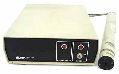
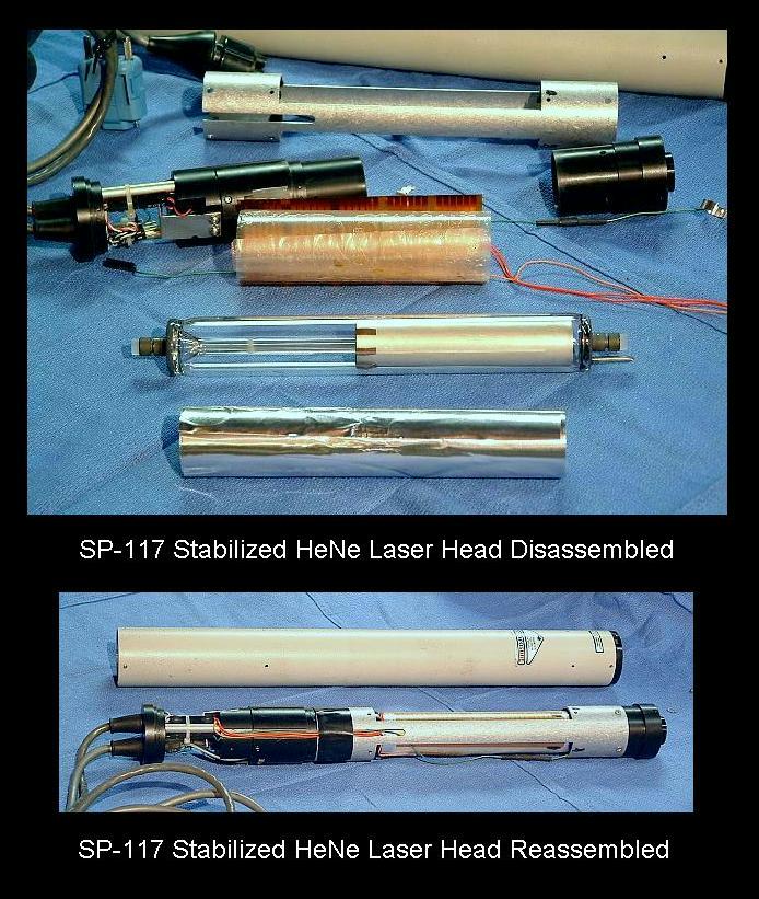
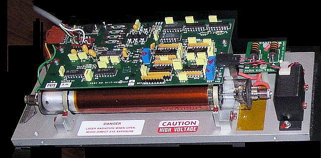
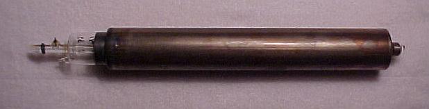
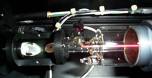
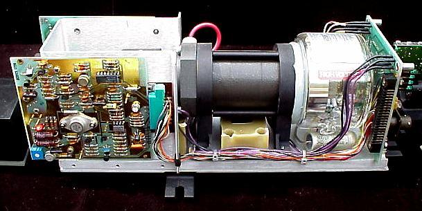
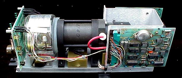
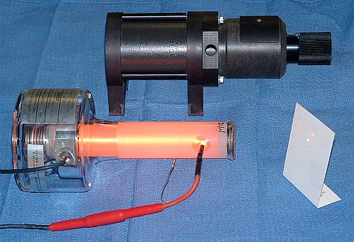
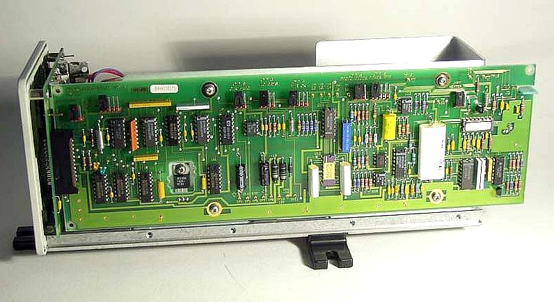
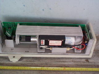
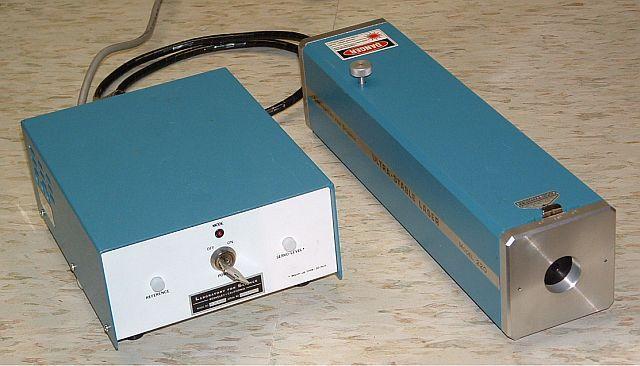
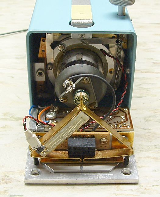
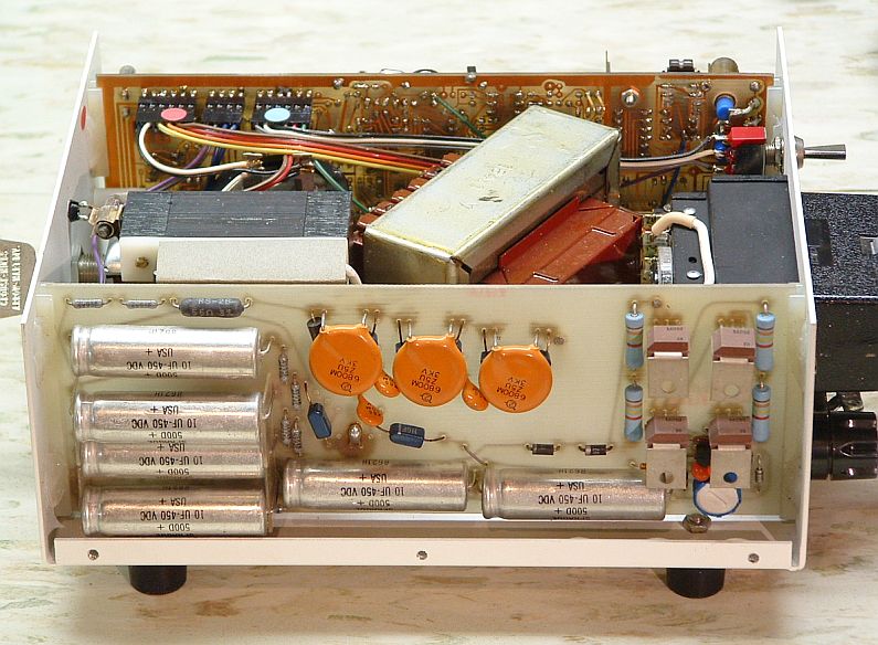
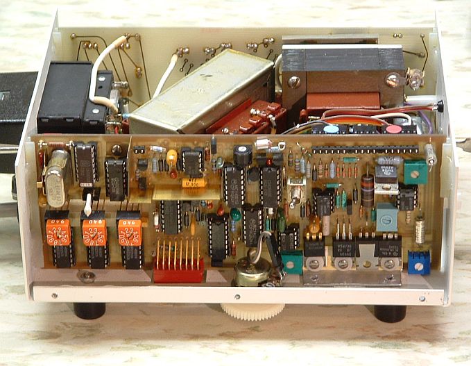
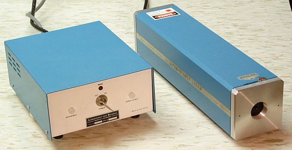
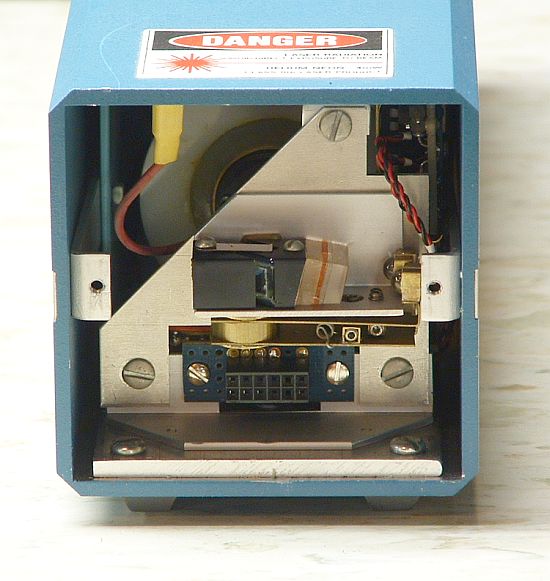
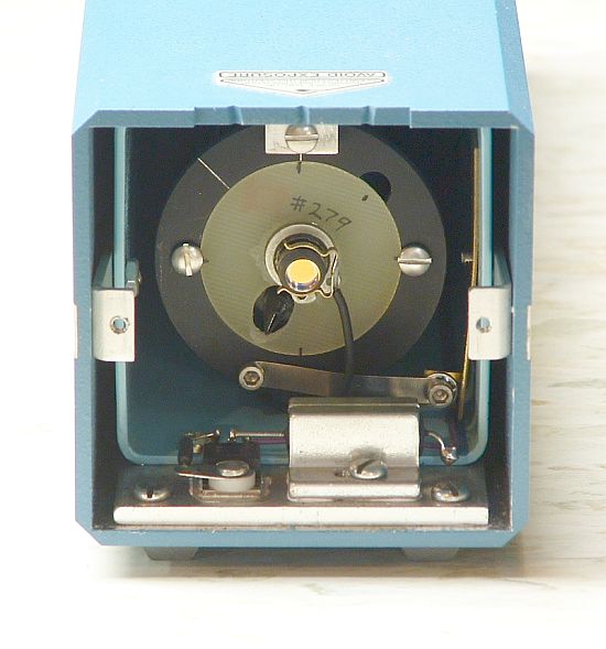
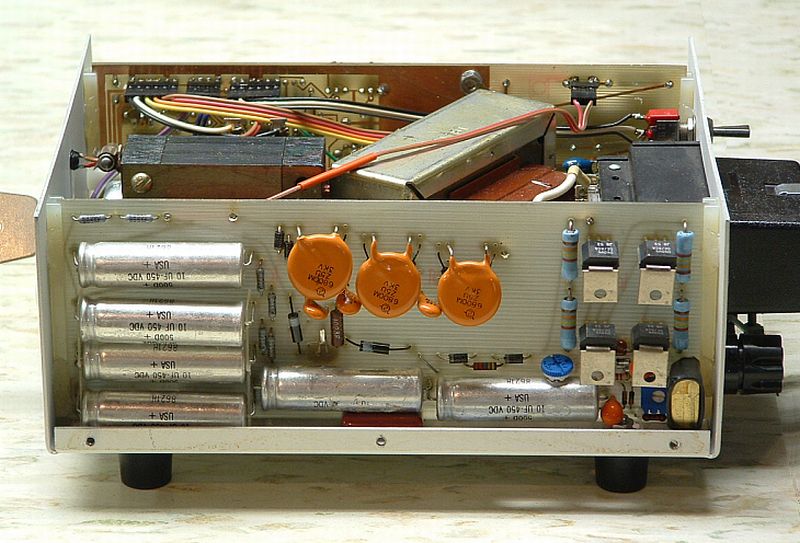
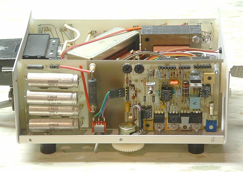
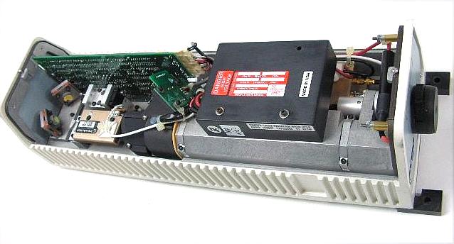