You Are Here: Greyghost > Features Page > Make Your Own Multiple Switched, Multiple Speed Furnace Fan
Make Your Own Multiple Switched, Multiple Speed Furnace Fan
(with a switch for each speed, and including safety features to protect the motor from stupidity)

PrefaceMulti-Speed Furnace Fan Wiring

This article is long overdue. Upon coming into possession of an old furnace blower assembly having multiple operating speeds, I got to thinking that it would be really nice to provide for a means of switching from one motor speed to another, all without exposing an end-user to an electrical hazard or the motor to errors in wiring (such as attempting to run more than one speed at a time). At the time, I shot a quick video giving an overview of what I'd done and promising a schematic at some point in the future.

That was in late 2009, and here it is, right in the middle of 2016. Nothing like that "getting things done" spirit, is there?

The obvious approach to implementing an easy to use system that would also protect the motor from stupidity or malice would be the use of a rotary switch. That is what I had initially planned to do, only I couldn't find a suitable switch anywhere. What I did find was any of not rated for mains voltage, not heavy enough for the kind of current I knew would be drawn, equipped with far too many or not enough switch poles or far too expensive. Around this time someone introduced me to the McMaster-Carr catalog. They seem to have one of about everything. It's this strength that is also their greatest weakness. I found it impossible to progressively drill down to something that'd do the trick.

Even if I would have found something suitable, I realized pretty quickly just how far off the beaten path I was treading. Time gets even with everything: stuff breaks, burns out, gets lost or thrown out and so on. Having to re-engineer my fan down the road at some point and being unable to find an exact match to whatever part I had used would be annoying to say the least. One of the key design goals fast became a matter of "how could this be done with common, off the shelf parts?"

I soon had an idea! It'd be easy to use three way switches to pass power to each speed winding in the fan motor OR passing it on to the next switch in line, all the way up to the highest speed. I'd wire the switches in something of a "ladder" formation, thus assuring that no more than one motor winding could ever be energized at any time. Each three way switch would compose a simple logic circuit, enabling one choice OR another. Any attempt to energize multiple speeds at once would be ignored, or result in the motor simply safely dropping to a lower speed. A single way switch would represent the final motor speed (highest or lowest, I chose highest).

Rounding things out were an electrical cord set, a few switch boxes, some scrap wire, crimp-type connectors, some zip ties for strain relief, and a few wire clamps. Stuff you will need in order to this yourself will include a (decent) multimeter, basic working knowledge of electricity and how to handle it safely, a wire cutter, wire stripper, some screws, assorted light switches, switch boxes, and maybe even some sheet metal (if like mine, your furnace fan of choice labors without some restriction on its output).

In an effort to channel my "unique" sense of humor into a useful capacity during this project, I selected a light switch having a brilliant RED toggle to represent the high speed. A red switch can signify danger and a reason to be cautious. Here I believe it would be best said to indicate a need to hold on to your hat! Or anyone's hats for quite some distance, actually.

A lot of people have asked about how to wire something like this. Until I demonstrated my fan to an HVAC class, I'd never written anything up detailing its operation or providing for schematics. Here it is, at long last. Everything below remains more or less as it was written in the handout I gave to each of my fellow students. But first, a word about the most important things of all: your safety and that of others.

(I realize that my choice of title for this page is somewhere between awkward and lame. If you've got a better idea, suggestions are welcome. Until such time as I get a title I like, anyway. This page is also in a PRERELEASE BETA STATE. Further changes, clarifications, additions, corrections and anything else unlucky enough to wander by as I am wielding my keyboard are HIGHLY LIKELY to take place! In other words, check back often!)

WARNING!

Any project involving the use of electricity is potentially DANGEROUS!

You can be badly hurt or even killed by a lot less electricity than you might think! Even a tiny current is enough to potentially stop your heart, if it can get there. AC power as delivered by your electrical utility is even more dangerous than many other sources of electrical energy: the essentially unlimited current that's available can result in your being badly burned, blinded, hurt in other ways or KILLED.

If you are not ABSOLUTELY CERTAIN of how to work with electricity safely, DO NOT attempt to do so. Likewise if you do not understand how to wire something in a safe and correct manner: AC line power is NOT the place to practice, as mistakes are all too often fatal.

This is ABSOLUTELY NOT a joke!

Never work on ANY electrical device unless you are CERTAIN that power has been disconnected.

Lock out and CLEARLY LABEL any electrical disconnects, circuit breakers or fuses so that no can accidentally or unknowingly energize a circuit you or anyone else happens to be working on.

Introduction

A multi-speed motor often has its speeds represented by multiple wire connection points known as taps. At no time should more than one of these speed taps be supplied with electricity. The motor could be damaged or operate improperly if more than one speed tap is energized at any given time. A risk of injury is also present if motor operators are expected to handle electrical wiring themselves in order to change motor speeds.

A complete solution to these problems is realized by pre-wiring the motor in such a way that all speeds are available without any need for rewiring, and no more than one speed may ever be selected at any given time. The operator need not have any understanding of electrical wiring or motor theory. They need only understand how to plug in an electrical cord set and operate a switch.

Theory Of Operation

A permanent split capacitor induction motor featuring multiple speeds is at the center of this design. Four speeds are available: low, medium-low, medium-high and high.

Power is supplied to the motor by way of a rugged twelve gauge power cord assembly having a grounded electrical plug attached to it. Power from this cord assembly is brought to a switch  having a pilot light. This light indicates only that power is available. It cannot indicate whether the power is of the correct type or sufficient to operate the load.

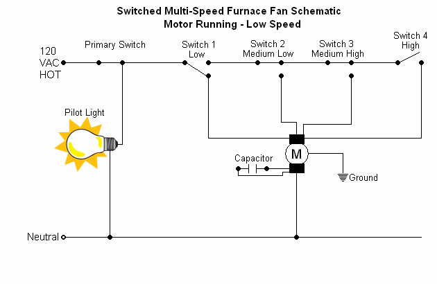
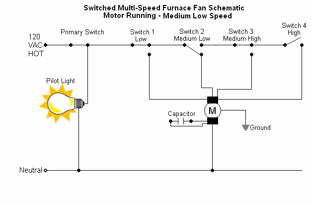
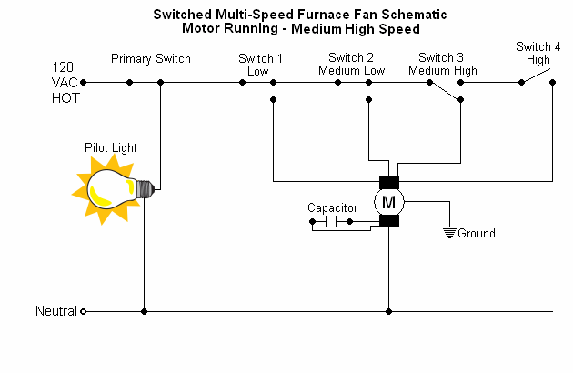
From the primary switch and pilot light, power is sent first to a bank of three way switches. The three way switches have been wired such that electrical power is directed in one of two ways depending upon switch position:
There are three of these three way switches to represent the motor's first three available speeds. The last available speed is selected with a one way switch. Being as there are no more speeds available from the motor, there is no need for the last switch to pass power to another switch.

Switches representing lower speeds always have priority over the switches representing higher speeds, as indicated in the table on page two. Only one switch should be turned on in the course of normal operation, but if multiple switches are turned on, no damage will be done.

Motor Speeds vs. Switch Position

Switch #/Type

Motor Speed

Switch Four On

(One Way)


HIGH

Switch Three On

(Three Way)


MEDIUM

HIGH


Switch Two On

(Three Way


MEDIUM

LOW


Switch One On

(Three Way)

LOW


Switch Wiring (not in the original, but here in the name of being thorough)

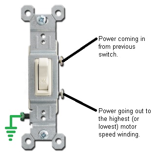
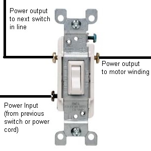
Each of the first three speed switches is a three way type, wired such that power can be directed one of two ways: to the next switch in line, or to a speed winding in the motor. Since a picture's worth a thousand words, here's one right now. (I'd like to take a moment and comment on how surprised I was not to find any pictures of a three way switch on the Internet that were worth appropriating. So once again, in my selfless commitment to this site's viewers...I whipped out Windows Paint and Did It Myself.)

Your mileage may obviously vary depending upon the exact type of fan, switches and other stuff you have. Use your brain, and don't be stupid. (See the Big Red Warning above. And don't even think you're going to sue me based on your inability to follow these instructions and/or work with electricity safely. You're welcome to all of the nothing I have, which is really quite a bit.)

Three way switch, illustrating the needed wiring connections.
Of the two power output connectors on the switch, it doesn't matter which one goes to the motor or to the next switch in line. Do whatever's most convenient for your situation.

The final switch is a single way type, and has only two connections: one bringing power to it and another passing power to the motor's highest (or lowest) speed. I made the decision to wire the speeds in ascending order (lowest to highest), but there is no reason why you couldn't do the opposite.

One way switch wiring diagram, representing the final fan speed selection.

Your primary switch, should you decide to use one, is wired similarly to the final speed switch. Power comes in (from your power cord) on one side of the switch and goes out the other, on its way to the pilot light (if you decide to include one) and the bank of switches that will let you choose a given motor speed.

Don't switch the neutral side of the line. For your own safety, connect all the grounds, and only use your furnace fan where properly grounded outlets are available. Thoroughly insulate any potentially exposed connections.

Schematics
(for all possible operating modes)


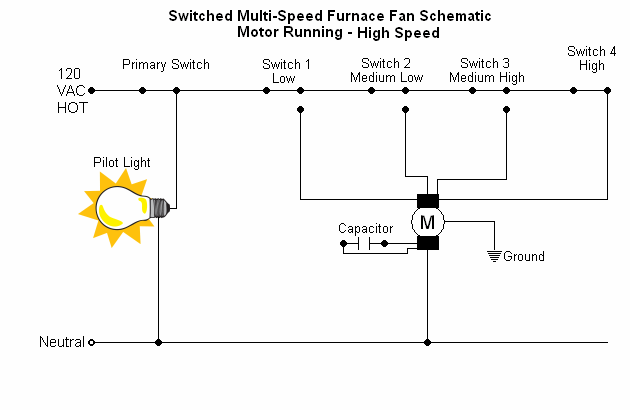
These require image display to be enabled within your web browser. This is exactly how I wired my furnace fan up. Your mileage may vary, depending upon what you have.

Schematic #1 - All Power Off

Schematic #2 - Pilot Light On, Fan Off

Schematic #3 - Fan Running, Low Speed

Schematic #4 - Fan Running, Medium Low Speed

Schematic #5 - Fan Running, Medium High Speed

Schematic #6 - Fan Running, High Speed
And that's pretty much all there is to it. As always, please do feel free to contact me with your experiences, questions and comments. If you are unfamiliar with electricity and switching logic, I wouldn't recommend this as a first project. Start out with something simpler, like rewiring a lamp or building a switched light.

Enclosures and Final Touches

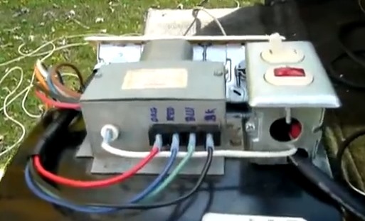
In order to safely enclose each switch and wiring point, I used metal junction boxes that were screwed into the fan's body. In the case of my fan, there was more than enough clearance to drive screws into the outer shell. One of the hardest things to find was the switch plate I used to cover up the switches and their wiring. Steel switch plates wouldn't seem to be an uncommon thing, but it took me quite a while to find anyone actually selling such things.

In order to keep the power cord from becoming cut or snarled up in the blower wheel and to reduce the stress of handling on any electrical connections, I zip tied it off at various points. Don't abuse or stretch the cable when doing this. Just make sure that slack in the cable is kept to a minimum.

Other finishing touches included a wooden base and a partial restriction over the output to reduce load on the motor. (Check this with an ammeter and compare it to your motor's printed specifications. If the amount of current drawn grossly exceeds the motor's rating, you probably need a restriction covering some of the output.

Rounding things out was a carrying handle, again screwed into the blower wheel body. It's very sturdy and makes carrying the thing (which is rather heavy) a lot easier.

(By the way: don't even THINK of stealing this page or any of the images on it. Whether you may believe it or not, I will very probably find out. You are permitted to reproduce this page per the terms and conditions governing your use of materials hosted on this server, so long as you provide credit, do not charge or exchange items of value for access to these materials and no advertising material is displayed alongside the resource in question.)

Go Back > (to Features page)


Coypright © 2009-2016 by William R. Walsh. Some rights reserved. Terms and conditions governing your use of this material are available at the top level page of this server. Please read them. Don't mess around with electricity unless and until you FULLY understand what you are doing and how to do so safely. This information is presented in good faith, but without warranty of any kind whatsoever. You and you alone are responsible for the results of your actions. I disclaim any and all liability to the maximum extent possible under law, along with any and all liability arising from incidental or consequential damages. Electricity is very useful, but it is also absolutely NOT to be trifled with.

Last updated: 06/20/2016