You Are Here: Greyghost > Features > Sears Crafstman Professional 82325 Datalogging Multimeter
Sears Craftsman Professional 82325 Datalogging Multimeter

Out of all the Sears Craftsman branded datalogging digital multimeters I've looked at so far, this one has by far and away the hokiest software. The meter seems fairly decent. It also appears to be much less common than the other ones I've looked at in the past. So, let's dive into the retrotechnology mine once again.

The complete model number for this meter is 242.82325.0. As usual, the first three digits indicate the actual manufacturer (Saftec).

I don't have any parts or pieces available for these meters, and I don't know where (if anywhere) you could find them. Your best bet is probably just to buy another meter as a replacement, or look for something newer. Uni-Trend's UT61E+ is a decent choice for a meter with PC connection and datalogging capability.

The Software

You're probably here not because you care what some angry raving loony on the Internet has to say about a twenty-plus year old multimeter, but rather because you have one of these and need the software that goes with it. It's here that I have good and bad news for you. The diskette I got with my example of this meter was heavily damaged. Luckily, the actual data logging program, once I'd unearthed it from InstallShield's incredibly stupid proprietary cabinet archives, proved to be undamaged. There are download links a little further down if that's all you care about.

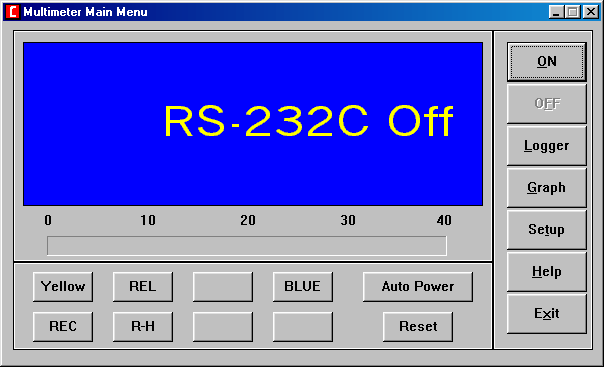
The software itself is very hokey. It flickers noticeably when the reading updates, doesn't let you set an update interval, seemingly doesn't come with the text file that the "help" button calls up, and has several crudely blanked out buttons that likely represent features not offered in this meter. It also tries to assume direct control of the serial port, making it a total nonstarter for use under any modern version of Windows. If you've got an old computer around that's still pushing Windows 95, 98 or (heaven forbid) Windows Me, you'll need it. (I also tried it under Wine, with a 32-bit wineprefix set up to behave as though it were Windows 98, and it wasn't having any of that either.)

If you plan to download and use the software, that's entirely on you. What I have came from a damaged diskette and while it worked for me, it might toss your entire computer into a nearby lake. Don't come complaining to me if or when it does something bad. You'll need a few runtime DLLs, though most Windows systems should have them. There's also a TrueType font that I was unable to rescue which likely provides a segmented display font for the software to use. At least for me, what it fell back on was readable enough. Perhaps the damaged diskette is why I could not come up with the "help" text file, though I don't really buy this as I could see the other damaged files within the cabinet archives, indicated as being of zero length.

Consider yourself warned. If you're still feeling brave, click here. For whatever good it'll do you, I also have an image file of the heavily damaged diskette. It was created in WinImage but should work with other popular disk imaging programs. I'd like to thank the developer of UniExtract for making it possible to extract things from the idiotically non-standard InstallShield cabinet archives.

If you have the undamaged software for this meter, I'd love to hear from you. You may require some common Microsoft runtime libraries. If you do, the program will identify what you need in the error message it displays. When you go off in search of these, be sure to get them only from trustworthy sources.

I've seen no indication that open-source datalogging software like Sigrok has any support for this meter, or one like it. Nor have I tried it myself, to see if it works anyway. (I've never gotten Sigrok to do anything useful with any meter, for whatever that is worth.)

There exist other meters (see below) that use the same unusual serial cable. Unfortunately, it's suggested that the software differs noticeably between each one, and is not interchangeable. I'd still be interested in saving that software if anyone has it.

Craftsman 82325 datalogging multimeter software

Note the blank buttons in the software above. One wonders what they might have been for, if anything. Unfortunately, poking around with various disassembly tools and Resource Hacker didn't turn up much. The protocol appears to be bidirectional, as one can send a few commands to the meter. ("Yellow" and "blue" correspond to buttons on the meter, as do all of "REC", "R-H" and "REL".

The Meter

...was manufactured by Saftec for Sears. Saftec manufactured at least one other model, and likely several, for Sears over time. Near as I can tell, Saftec is long defunct and seems to have gone quietly. If you have more information about the company, I'd love to hear from you. (However, Brymen Technology Corporation's BM850S and BM810S meters do look extremely similar.)

Beyond this page, there's little to no information online about the Sears version of this meter. A little poking around has suggested that the Voltcraft VC350E is the same basic meter. Saftec also produced it under their own name as the SAF350E. Software is said not to be interchangeable between the Voltcraft and Saftec. Presumably the same is also true for the 82325.

Beyond all of that, it's your typical autoranging digital multimeter with test ranges for AC and DC voltage (including millivolts for DC measurements), resistance, continuity, diode check, frequency counter, capacitance and temperature. AC voltage and current measurements are average-responding, rather than true RMS. Measurement of nonsinusoidal AC waveforms will result in misleading values being displayed.

Current testing ranges for both AC and DC voltages include microamps, milliamps and amperes to a maximum of twenty amps. There are separate jacks for temperature, current and capacitance testing. All current testing jacks are protected by fuses. The meter's beeper will sound an alarm if the test leads are connected to the current testing jacks while in voltage, resistance, continuity, diode test or frequency counter mode. No similar warning is provided if the test leads are connected to the voltage/resistance/frequency counter input.

The Display

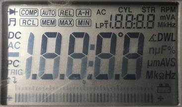
Small 82325 multimeter display panel, with all characters displayed. (Click to see it larger.)

...has a great many extra indicators for functionality not present in this model. Most seem to have to do with some sort of automotive engine analyzer functionality. Although the small set of seven segment digits is utilized, it's not as fully utilized as it could have been. It's primarily used in the relative, maximum, minimum, and memory storage modes. It could have been, but is not, used as a frequency counter display when measuring AC voltage or current.

Specifications and Accuracy

The manual tells us this about accuracy and resolution in each test range:

Function
Range
Resolution
Accuracy
DC mV
400mV
100µV
±0.3% reading + 2 digits
DC Volts
4
40
400
100V
1mV
10mV
100mV
1V
±0.3% reading + 2 digits


±0.5% reading + 2 digits
AC Volts
40-100 Hz
(not TRMS!)
4V
40V
400V
750V
1 mV
10mV
100mV
1V
±0.8% reading + 3 digits


±1.2% reading + 5 digits
DC Current
400µA
4000µA
40mA
400mA
4A
20A
0.1µA
1µA
10µA
100µA
1mA
10mA
±0.5% reading + 2 digits


±1.0% reading + 5 digits
AC Current
40-100 Hz
(not TRMS!)
400µA
4000µA
40mA
400mA
4A
20A
0.1µA
1µA
10µA
100µA
1mA
10mA
±0.8% reading + 2 digits


±1.5% reading + 10 digits (!)
Resistance
400Ω
4kΩ
40kΩ
400kΩ
4MΩ
40MΩ
0.1Ω

10Ω
100Ω
1kΩ
10kΩ
±0.8% reading + 2 digits
±0.5% reading + 2 digits


±1.0% reading + 10 digits
Capacitance
100nf to
100µF

100µF to
400µF
10pF


1µF
+3.0% reading + 10 digits (!)


+5.0% reading + 10 digits (!)
Temperature
-40°F to
1999°F
- or -
-40°C to
1000°C
1°F*


1°C*
±3.0% reading + 5 digits
Frequency
40 Hz to
1 kHz

1 kHz to
2 MHz
1 Hz
±1.0% reading + 5 digits


±0.3% reading + 3 digits (!)

* there is an error in the manual, where the °C and °F were swapped in the "resolution" column
(!) denotes an interesting value, and is not part of the original manual's text

Frequency input sensitivity from 10 Hz to 10 kHz is 1 volt. From 11 kHz up to 2 MHz, frequency input sensitivity is 500mV. No indication is given, and I've not tested to see if a zero crossing point is required for the frequency counter to operate. When measuring frequency, the input voltage is limited to 250 volts.
Diode testing current is 1 mA.

The meter will test capacitors far in excess of its published specifications. I tested a 10V, 1000µF capacitor and the meter was able to do so in a reasonable length of time with accurate results.

Other Stuff (pertaining to meter operations, mostly from the operator's manual, which I have and might scan someday)

The audible continuity test functions in an interesting and unusual way. Different resistance ranges (up to 1700 ohms) sound differing types of tones from the meter's built in beeper. For resistances below 30 ohms, the tone will be continuous. From 31-105 ohms, a fast intermittent tone will sound. Between 106-1700 ohms, a slow intermittent tone will sound. No tone will be heard, and the meter will give an open loop ("OL") indication in audible continuity mode above 1700 ohms.

Sears indicates the input impedance to be 10M ohms, with a quoted capacitance of 100pF.

There are two special purpose buttons on the meter. The BLUE button changes functions (e.g., DC to AC volts) while the YELLOW button selects between temperature measurement or the "fuse test" modes. All the other buttons are discussed in the manual, which I'll get around to scanning and posting here at some point. There are some interesting functions offered by this meter. There is an automatic power off timer that may be bypassed by holding down the BLUE button while turning the power on. Doing the same with the yellow button results in a curious "60 Hz" display. One can toggle this display between 50 and 60 Hz with the REL and COMP buttons. It's not clear, nor discussed in the manual, what purpose this serves.

Settings you specifiy for each testing range are not remembered, even if you change ranges and the power remains on. Data stored in the meter's comparison and min/max memories is not saved when the power is shut off.

A special connector exists on the meter, into which capacitors or type K thermocouples could be inserted. You cannot make capacitance measurements using the regular test leads, which is kind of a pain if the capacitor you want to test doesn't happen to plug into the special connector. A crude way around this would be to jam wires into the connector, using care not to break or distort its internal contacts. Testing new capacitors with their differing lead lengths was also something of a pain.

This meter bases on the Maxim Integrated Products MAX134, a datasheet for which is here. Being as this only an A/D converter, there's a microcontroller lurking somewhere within. I didn't try to find it.

Serial Cable

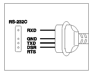
Beyond the data logging software linked above, you'll also need an appropriate cable to connect the 82325 multimeter to your computer This is, to say the least, a nonstandard cable. Good luck finding one! (No, I haven't got any spares. Nor do I know where you can buy one.)

Craftsman 82325 Serial Cable Pinout
Note that I've not personally verified whether this is correct. This cable's got the potential to be more than a little hazardous to the health of your serial ports, due to the large exposed pins. At least a protective boot is provided to cover them when not in use, if you think to use it. It doesn't fit very tightly into the mating holes on the meter. I don't know how well it'd hold up under heavy or repeated use.

With my particular meter, serial communications took place at 1200 bits per second, eight data bits, two stop bits and no parity.

Serial Protocol Investigation

As mentioned above, communications take place at 1200 bits per second, with eight data bits, two stop bits and no parity. There doesn't seem to be any third party support for the various Saftec protocols. Using a very old version of the SysInternals PortMon software, I did a little eavesdropping on the serial communications between the meter and its software. I'd welcome any input anyone has on decoding the protocol. Unfortunately, I don't remember what I was measuring at the time, nor which commands I sent to the meter during these sessions. I've also managed to misplace the serial cable, otherwise I'd go through each mode of operation and capture data from it.

The software supports sending a few commands to the multimeter and apparently places it in the datalogging mode (which in addition to disabling the auto power off timer, also turns on the "PC" indicator on the meter's display). I'm not sure that either of these actually ended up meaning anything, nor do I remember what I was measuring or which measurement mode the meter was in. I think I've got some hex dumps, but haven't posted those.

Session 1
Session 2

Going after these required venturing into Windows 98, something I've not done in years. Being as I couldn't readily put hands on an actual computer running Windows 98 without substantially cleaning up the Computer Mess Room®, I took the easy way out and fired up an old VMware virtual machine after assigning the host's serial port to it. I was duly impressed that such chicanery actually worked.

Until such time as I've actually found the serial cable, that's as much as I can give you about the protocol. If you do plan to look into it further and want more information, just drop me a line.

The Manual

I have a copy of the owner's manual for this meter. Hopefully I can be bothered to scan it at some point, but I don't know when that might be. If you're desperate to know something about it, send me an e-mail.

Disassembly (of the actual meter, not the software)

If you don't have to, I wouldn't. The meter casing is pretty fragile and it's held in place by plastic snaps in addition to screws. One of the posts into which a screw threaded in my example of this meter was broken. It felt as though the casing would break as I was trying to get it apart. You'll have to remove the rubber holster, which is also fairly fragile. Whether due (again) to age or just the nature of the beast, I don't know.

The fuses and battery are changed from the front. Turn the meter off, disconnect the test leads from it, remove the holster and the two lower case screws. Lift the lower part of the front panel off to reveal the battery and fuses.

Somewhere in its past, someone blew the high current fuse in my example of this meter. It's a Bussman BP/ABC-20 fuse, often found in microwave ovens. Many different places sell these. No matter how tempting it might be, do not replace this fuse with a glass type. The ceramic body and sand within the fuse serve to quench an arc, should one take place when the fuse blows. A glass fuse could explode and contains nothing to help extinguish an arc.

Links N Such

These are some random articles and pieces of information I came across while researching to prepare this page. As always, I make no guarantees that any of the below linked sites are relevant, still online or even safe to visit. (This page has been moldering on my "to do" list since early 2019, not long after I bought the meter and set in to exploring it.)

Voltcraft VC-350E
Some information about the Voltcraft meter's cable and protocol (originally in Polish)
What looks like a download link to the instructions for the SAF 350E meter (maybe some kind Polish speaker would send them to me?)

Things To Come In Future (though I make no guarantee of when!)

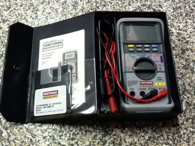
I need to take a picture of my own meter, scan the manual, find the long lost serial cable, and explore the serial protocol in greater detail. For now, if you're really interested in seeing a picture of the complete meter set, I swiped the one below from here. (The author of that page has misidentified the 82325 meter as an 82324. Unfortunately, the software they are providing is definitely for the 82324 meter.)

Sears Craftsman Professional 82325 digital multimeter

The disk included in the picture above looks to be of much better quality than mine. If it weren't for the label, I'd swear mine was a "homemade" duplicate. My disk is green in color and has a plastic shutter with a brand name on it. I'll get a picture at some point.


Go Back>

Original text and images copyright © 2019-2020 by William R. Walsh. Some rights reserved. Your use and reuse of this material is governed by the terms and conditions available from the top level page of this server. Originally written on March 24th, 2019 at 8:36 PM. Later updated and published on November 29th, 2020. Other materials presented on this page remain the property of their owners.