After Midnight Hacking With William
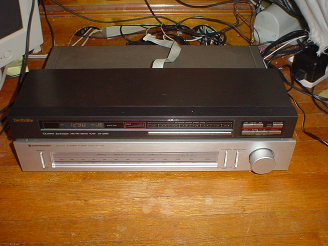
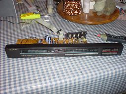
Hacking The Technics ST-Z990 AM/FM Stereo Tuner
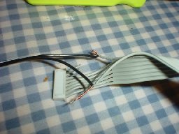
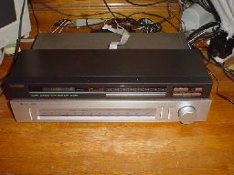
I have been looking for a standalone AM/FM tuner for a long time now. Over the years I had tried to get one, but I never actually managed to get this done. Recently, an analog-tuned Kenwood tuner and a Technics ST-Z990 tuner followed me home. The Kenwood is in excellent working order, but the Technics unit came with a small catch...it has no standard audio or power cables whatsoever! There is only a single ribbon cable coming out of the back of the unit. It is intended strictly for use with a special Technics amplifier or other module that can provide a means of connection for the tuner.
At first I was not overly optimistic about making this tuner work. I could find nothing on the web about a pinout and a post to the sci.electronics.repair newsgroup didn't generate any replies. About this time I got to feeling mighty bold and I cracked the case on the tuner to see what was inside. Upon discovering and looking at the ribbon cable connector on the circuit board, I found that it was labeled with crude descriptions of pin function. Two pins were marked "AC".
At this point, I decided to hack it and post the results here for others to benefit from.
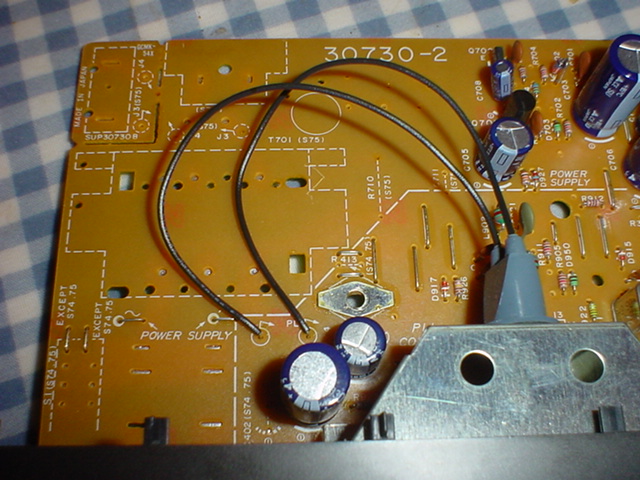
I started by tracing out the circuit to be sure that the "AC" pins were in fact power carriers. Careful trace work with a fine point pen and a close eye to detail revealed that the "AC" pins on the connector lead directly to the lamp for the tuner display and a totally unpopulated power supply/switch area on the tuner board. This and other tuners I have found of a similar design seem to suggest that "normal" versions of this tuner with a regular power cord and line outs were made.
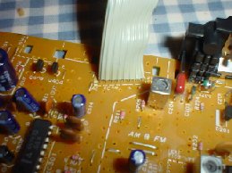
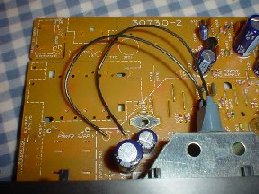
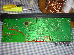
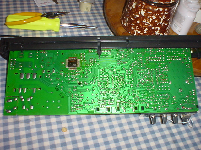
Pictures: Large Highlighted Version - Unedited Version - Pilot Light Connectors & PSU area
With this in mind, I cut the two "AC" marked wires away from the plastic connector. I finally found a 9 volt AC, 600mA power block and tested it with no load. The output wasn't as stable as I had hoped for, but it would have to do as all the other adapters I had were way high on voltage when unloaded.
I then connected the leads from the wall-wart power supply to the tuner itself.
WARNING/CAUTION: Working with line powered equipment can be dangerous if not done properly. While the low voltages and relatively low currents used here are not likely to be of much concern, they could still cause injury to you or fatal damage to your equipment. Always remember to be very careful when working with any sort of line powered circuit or apparatus. Don't do anything like this if you don't have a good understanding of how to work with electricity safely.
Modifying this tuner to run off a more standard form of power is way outside the realm of Technics' original design and intention. It will void any sort of warranty or service contract that your stereo system or tuner may be covered under. If you're not sure if your set is under warranty--don't do this! It is also not known at this time if this approach to operating this tuner is reliable and sustainable. The chance exists that this tuner will fail since it is being used in a way that it was not originally designed to be used.
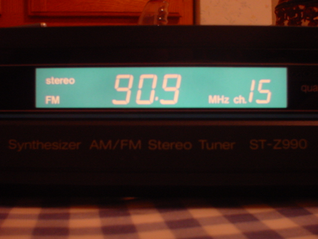
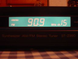
After taking a deep breath, I worked up my courage and plugged the cord set into the wall. To my relief, the tuner came on immediately and the display lit up. Pushing the buttons showed it was working for pretty much all intents and purposes.
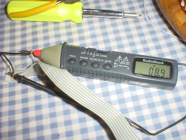
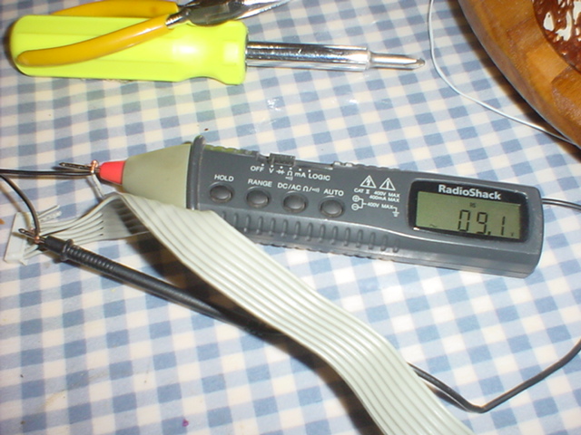
It was about this time that I shut the tuner down because I noticed a transistor on the board getting very hot in operation after several minutes. It never burned up or showed signs of becoming unstable, but I wondered if the 600mA rating of my adapter was enough to keep the tuner happy. To determine this, I pulled out my "stick meter"...a Radio Shack DMM built into a nice "probe like" package and stuck it on the power inputs to the tuner.
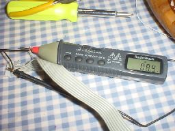
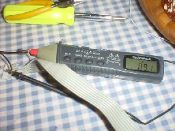
Sure enough, the power output of my adapter didn't seem to be sufficient. It seemed to be fine on the AM band, but upon switching over to FM Stereo and getting a lock on a station, the voltage dropped and that transistor got really hot. I had kind of suspected that this unit pulled more power than any 600mA anyway, what with all of the pilot light, LEDs, and digital tuner circuit.
For now this is all I have done with this project. Presently I have not yet uncovered the audio outputs on the tuner, nor have I explored the functionality of other not-so-well labeled wires in the ribbon cable. The audio outputs are at least labeled, so it is just a matter of time before I hook them up and get the wiring figured out. As for the other wires, there is a set of pins that appears to feed signals from a remote control into the tuner. I don't know if I will bother with these or not at this time.
I also have plans to secure a bigger power supply. Right now I have a 1 amp, 9VAC wall adapter from an unused US Robotics 33.6K modem. I may use this at least temporarily to power the tuner. It would be my hope that this power supply would be more than enough.
Should the transistor inside still get too hot for comfort, I will fashion a heat sink to help relieve the thermal burden on this part.
More Big Pictures
Go Back>
Copyright ©2005 by William R. Walsh. All Rights Reserved.