For contact info, please see the Sci.Electronics.Repair FAQ Email Links Page.
Copyright © 1994-2007
Reproduction of this document in whole or in part is permitted if both of the
following conditions are satisfied:
1. This notice is included in its entirety at the beginning.
We will not be responsible for damage to equipment, your ego, county wide
power outages, spontaneously generated mini (or larger) black holes, planetary
disruptions, or personal injury or worse that may result from the use of this
material.
Most of us take all of this for granted rarely giving any thought to
the amazing interplay of precision optics and complex electronics - at
least until something goes wrong. The purpose of this document is to
provide enough background on CD technology and troubleshooting guidance
so that anyone who is reasonably handy whether a homeowner, experimenter,
hobbiest, tinkerer, or engineer, can identify and repair many problems
with CD players and possibly laserdisc players, CDROM drives, and optical
storage drives as well.
Even if you have trouble changing a light bulb and do not know which end of
a soldering iron is the one to avoid, reading through this document will
enable you to be more knowledgeable about your CD player. Then, if you
decide to have it professionally repaired, you will have a better chance of
recognizing incompetence or down right dishonesty when dealing with the
service technician. For example, a bad laser is not the most likely cause
of a player that fails to play discs - it is actually fairly far down on the
list of typical faults. A dirty lens is most likely. There - you learned
something already!
The primary differences between these types will relate to how the disc is
loaded - portables usually are top loaders without a loading drawer or tray:
However, as a result of the level of miniaturization required for portables
and to a lesser extent, CDROM drives, everything is tiny and most or all of
the electrical components are surface mounted on both sides of an often
inaccessible printed circuit board with the entire unit assembled using
screws with a mind of their own and a desire to be lost.
For other types:
Note that throughout this document, the term 'CD player' is used most often.
However, it should be understood that in most cases, the information applies
to CDROM drives, game machines using CDs like the Sony Playstation, laserdisc
players, MiniDisk players/recorders, DVD players, and other types of optical
disk systems. Also see the document specifically devoted to these other
technologies: "Notes on the Troubleshooting and Repair
of Optical Disc Players and Optical Data Storage Drives". Also, where I
remember, the term 'disc' is used to denote a read-only medium (e.g. a
regular audio CD or LD) while 'disk' is used for one that is recordable
(e.g., CD-R or MiniDisk).
Note: Links to all the diagrams and photographs referenced from this document
can be found in Sam's CD FAQ Files.
Even many professionals may mistake (either accidentally or on purpose)
these symptoms being due to much more serious (and expensive) faults.
Don't be fooled!
Cleaning of the lens and any other accessible optical components (usually
only the turning mirror, if that) and a mechanical inspection should be the
first things done for any of these problems (and as periodic preventive
maintenance especially if the equipment is used in a less than ideal
environment). See the section: General inspection,
cleaning, and lubrication.
You can often repair a CD player which is faulty due to (1) or (2) except
for laser power which I would not attempt except as a last resort without
a service manual and/or proper instrumentation if needed - improper adjustment
can ruin the laser. If discs are recognized at all or even if the unit only
focuses correctly, then laser power is probably ok. While the laser diodes
can and do fail, don't assume that every CD player problem is laser related.
In fact, only a small percentage (probably under 10%) are due to a failure
of the laser diode or its supporting circuitry. Mechanical problems such as
dirt and lubrication are most common followed by the need for electrical
(servo) adjustments.
The solutions to category (3) and (4) problems are obvious - but it may take
a conscious effort to remember to check these out before assuming that the
fault is due to something much more serious.
Category (5) failures in the power supply of component (AC line powered) CD
players can also be repaired fairly easily.
Most other electrical failures will be difficult to locate without the service
manual, test equipment, and a detailed understanding and familiarity with
audio CD technology. However, you might get lucky. I have successfully
repaired problems like a seek failure (replaced a driver chip because it was
running excessively hot) and a door sensor failure (traced circuitry to locate
a bad logic chip). Since so much of the intelligence of a CD player is in the
firmware - the program code inside the microcontroller, even the schematic may
be of only marginal value since I can pretty much guarantee that the firmware
will not be documented. The service manuals rarely explain *how* the equipment
is supposed to work - and then perhaps only in poorly translated Japanese!
You can pretty much forget about repairing electrical problems in portable
equipment other than perhaps bad connections (usually around the audio or
power jacks, internal connectors, interlock switch (since it is stressed), or
elsewhere due to the unit being dropped). Nearly everything in a portable
(and most CDROM drives for that matter though this is not quite as bad) is
itty-bitty surface mount components. There is generally only minimal useful
information printed on the circuit board. Tracing the wiring is a nightmare.
Even the test points and adjustments may be unmarked!
Therefore, unless you really do need a 250 disc CD changer with a
remote control that has more buttons than a B777 cockpit and 2000 track
programmability, a 10 year old CD player will sound just as good and
repair may not be a bad idea. Many older CD players are built more solidly
than those of today. Even some new high-end CD players may be built around
a mostly plastic optical deck and flimsy chassis.
If you need to send or take the CD player or CDROM drive to a service center,
the repair could easily exceed the cost of a new unit. Service centers
may charge up to $50 or more for providing an initial estimate of repair
costs but this will usually be credited toward the total cost of the repair
(of course, they may just jack this up to compensate for their bench time).
Parts costs are often grossly inflated as well - possibly due to a deliberate
effort on the part of manufacturers to discourage repair of older equipment.
However, these expensive parts do not really fail nearly as often as is
commonly believed - the laser is not the most likely component to be bad!
Despite this, you may find that even an 'authorized' repair center will want
to replace the expensive optical pickup even when this is not needed. I do
not know how much of this is due to dishonesty and how much to incompetence.
If you can do the repairs yourself, the equation changes dramatically as
your parts costs will be 1/2 to 1/4 of what a professional will charge
and of course your time is free. The educational aspects may also be
appealing. You will learn a lot in the process. Thus, it may make sense
to repair that bedraggled old boombox after all.
CD-Rs - recordable CDs use a slightly different construction. CD-R blanks
are prestamped with a spiral guide groove and then coated with an organic dye
layer followed by a gold film, resin, and label. The dye layer appears
greenish and deforms upon exposure to the focused writing laser beam to form
pits and lands.
DVDs or Digital Versatile Disks (or Digital Video
Disks depending on who you listen to) - implement a number of incremental
but very significant improvements in technology which in total add up to a
spectacular increase in information density - almost 10:1 for the same
size disc. These include higher frequency laser (670 or shorter visible
wavelength), closer track spacing, better encoding, and a double sided disc.
According to early reports on the final specifications, DVDs will be able
to store 8 times the audio of current CDs at a higher sampling rate and
bit resolution, 2 hours of MPEG encoded high quality movies, and
all kinds of other information. Raw data capacity is somewhere between
5 and 10 GBytes. See the section: Comparison of CD
and DVD Specifications for additional information.
And the "Blu-ray" standard uses a blue-violet laser
to achieve even higher capacity for multimedia and computer storage
applications. See the section: Comparison of CD, DVD,
BD Specifications
That is followed by extremely sophisticated coding of the resulting 16-bit
two's-complement samples (alternating between L and R channels) for the
purpose of error detection and correction. Finally, the data is converted to a
form suitable for the recording medium by Eight-to-Fourteen modulation (EFM)
and then written on a master disk using a precision laser cutting lathe. A
series of electroplating, stripping, and reproduction steps then produce
multiple 'stampers', which are used to actually create the discs you put in
your player (more below).
Of course, it is possible to create your own CDs with a modestly priced CD-R
recorder (which does not allow erasing or re-recording). Now, re-writable CD
technology with fully reusable discs enables recording and editing to be done
more like that on a cassette tape
Like a phonograph record, the information is recorded in a continuous spiral.
However, with a CD, this track (groove or row of pits - not to be confused
with the selections on a music CD) starts near the center of the CD and
spirals (counterclockwise when viewed from the label side) toward the outer
edge. The readout is through the 1.2 mm polycarbonate disc substrate to
he aluminized information layer just beneath the label. The total length
of the spiral track for a 74 minute disc is over 5,000 meters - which is more
than 3 miles in something like 20,000 revolutions of the disc!
The digital encoding for error detection and correction is called the
Cross Interleave Reed-Solomon Code or CIRC. To describe this as
simply as possible, the CIRC code consists of two parts: interleaving
of data so that a dropout or damage will be spread over enough physical area
(hopefully) to be reconstructed and a CRC (Cyclic Redundancy Check) like error
correcting code. Taken together, these two techniques are capable of some
remarkable error correction. The assumption here is that most errors will
occur in bursts as a result of dust specs, scratches, imperfections such as
pinholes in the aluminum coating, etc. For example, the codes are powerful
enough to totally recover a burst error of greater than 4,000 consecutive
bits - about 2.5 mm on the disc. With full error correction implemented (this
is not always the case with every CD player), it is possible to put a piece
of 2 mm tape radially on the disc or drill a 2 mm hole in the disc and have no
audio degradation. Some test CDs have just this type of defect introduced
deliberately.
Two approaches are taken with uncorrectable errors: interpolation and
muting. If good samples surround bad ones, then linear or higher
order interpolation may be used to reconstruct them. If too much data has
been lost, the audio is smoothly muted for a fraction of a second. Depending
on where these errors occur in relation to the musical context, even these
drastic measures may be undetectable to the human ear.
Note that the error correction for CDROM formats is even more involved
than for CD audio as any bit error is unacceptable. This is one of many
reasons why it is generally impossible to convert an audio CD player into a
CDROM drive. However, since nearly all CDROM drives are capable of playing
music CDs, much can be determined about the nature of a problem by first
testing a CDROM drive with a music CD.
Each byte of the processed information is converted into a 14 bit run length
limited code taken from a codebook (lookup table) such that there are no fewer
than 2 or more than 10 consecutive 0s between 1s. By then making the 1s
transitions from pit to land or land to pit, the minimum length of any feature
on the disc is no less than 3*p and no more than 11*p where p is 0.278 um.
This is called Eight-to-Fourteen Modulation - EFM. Thus the length of a pit
ranges from 0.833 to 3.054 um.
Each 14 bit code word has 3 additional sync and low frequency suppression bits
added for a total of 17 bits representing each 8 bit byte. Since a single bit
is 0.278 um, a byte is then represented in a linear space of 4.72 um. EFM in
conjunction with the sync bits assure that the average signal has no DC
component and that there are enough edges to reliably reconstruct the clock
for data readout. These words are combined into 588 bit frames. Each frame
contains 24 bytes of audio data (6 samples of L+R at 16 bits) and 8 bits of
information used to encode (across multiple frames) information like the time,
track, index, etc:
Information on a CD is recorded at a Constant Linear Velocity - CLV. This is
both good and bad. For CD audio - 1X speed - this CLV is about 1.2 meters per
second. (It really isn't quite constant due to non constant coding packing
density and data buffering but varies between about 1.2 and 1.4 meters per
second). CLV permits packing the maximum possible information on a disc since
it is recorded at the highest density regardless of location. However, for
high speed access, particularly for CDROM drives, it means there is a need to
rapidly change the speed of rotation of the disc when seeking between inner
and outer tracks. Of course, there is no inherent reason why for CDROMs, the
speed could not be kept constant meaning that data transfer rate would be
higher for the outer tracks than the inner ones. Modern CDROM drives with
specs that sound too good to be true (and are) may run at constant angular
speed achieving their claimed transfer rate only for data near the outer edge
of the disc.
Note that unlike a turntable, the instantaneous speed of the spindle is not
what determines the pitch of the audio signal. There is extensive buffering
in RAM inside the player used both as a FIFO to smooth out data read off of
the disc to ease the burden on the spindle servo as well as to provide
temporary storage for intermediate results during decoding and error
correction. Pitch (in the music sense) is determined by the data readout
clock - a crystal oscillator usually which controls the D/A and LSI chipset
timing. The only way to adjust pitch is to vary this clock. Some high-end
players include a pitch adjustment. Since the precision of the playback of
the any CD player is determined by a high quality quartz oscillator, wow and
flutter - key measures of the quality of phonograph turntables - are so small
as to be undetectable. Ultimately, the sampling frequency of 44.1 K samples
per second determines the audio output. For this, the average bit rate from
the disc is 4.321 M bits per second.
Tracks are spaced 1.6 micrometers apart - a track pitch of 1.6 um. (This is
the nominal specification but may vary somewhat and will be less on those CDs
that contain more than 74 minutes of music or 650 MB of data. However,
unlike LPs, the pitch is not affected in the slightest by the content.) Thus
a 12 cm disc has over 20,000 tracks for its 74 minutes of music. Of course,
unlike a hard disk and like a phonograph record, it is really one spiral track
over 3 miles long! However, as noted above, the starting point is near the
center of the disc. The width of the pits on a track is actually about 0.5
um. The focused laser beam is less than 2 um at the pits. Compare this to
an LP: A long long playing LP might have a bit over 72 minutes of music on
two sides or 36 minutes per side. (Most do not achieve anywhere near this
much music since the groove spacing needs to vary depending on how much bass
content the music has and wide grooves occupy more space.) At 33-1/3 rpm,
this is just over 1,200 grooves in about 4 inches compared to 20,000 tracks
on a CD in a space of just over 1.25 inches! The readout stylus for an LP
has a tip radius of perhaps 2 to 3 mils (50 to 75 um).
An LP is pressure pressed using a solid vinyl biscuit. A CD, on the other
hand, is not manufactured in this manner. CDs are replicated through
injection molding, where molten polycarbonate is injected into a mold under
high pressure. CDs *must* be manufactured in strict clean room environments.
On a side note, when LaserDiscs were released to market by MCA DiscoVision in
1978, this requirement wasn't recognized, or ignored by MCA Corporate in an
attempt to keep manufacturing costs of these silver platters down. The first
discs were manufactured in an environment similar to an LP plant. As a
result, the finished product, while looking visibly okay when observed
casually, had major problems playing reliably on many LaserDisc players.
Now, of course, we know better, although Pioneer recognized these requirements
far more quickly than MCA. Even RCA's Videodisc plant for their
needle-in-grove CED (SelectaVision Videodisc) format recognized these
requirements better than MCA! CED's market introduction in 1981 did not
start as catastrophically like LaserDisc did as a result.
At a constant linear velocity of about 1.2 meters per second, the required
tracking precision is astounding: Proper tracking of a CD is equivalent to
driving down a 10 foot wide highway (assuming an acceptable tracking error of
less than +/- 0.35 um) more than 3,200 miles for one second of play or over
14,400,000 miles for the entire disc without accidentally crossing lanes!
Actually, it is worse than this: focus must be maintained all this time to
better than 1 um as well (say, +/- 0.5 um). So, it is more like piloting a
aircraft down a 10 foot wide flight path at an altitude of about 12 miles (4
mm typical focal length objective lens) with an altitude error of less than
+/- 7 feet! All this while the target track below you is moving both
horizontally (CD and spindle runout of 0.35 mm) 1 mile and vertically (disc
warp and spindle wobble of up to 1 mm) 3 miles per revolution! In addition,
you are trying to ignore various types of garbage (smudges, fingerprints,
fibers, dust, etc.) below you which on this scale have mountain sized
dimensions. Sorry for the mixed units. My apologies to the rest of the world
where the proper units are used for everything).
The required precision is unbelievable but true using mass produced technology
that dates to the late 1970s. And, consider that a properly functioning CD
player is remarkably immune to small bumps and vibration - more so than an old
style turntable. All based on the reflection of a fraction of a mW of
invisible laser light!
Of course, this is just another day in the entertainment center for the CD
player's servo systems. Better hope that our technological skills are never
lost - a phonograph record can be played using the thorn from a rosebush using
a potter's wheel for a turntable. Just a bit more technology is needed to
read and interpret the contents of a CD!
And, for a DVD with its narrower longer track (0.74 um compared to 1.6 um
and more than twice as long), it's even more of a challenge!
Wrong.
First, laser light that remains precisely parallel - doesn't diverge - only
can be found in bad Sci-Fi. Laser light still obeys the laws of physics and
in order to get the required spot size on the disc - about 1 micrometer (um),
1,000th of a mm, 1,000,000th of a meter, it needs to be focused precisely at
the disc surface. Due to manufacturing tolerances for disc flatness (warp),
the surface may move up-and-down as much as 100 times this amount. And disc
height from player to player isn't that precise either. Large diameter laser
beams can be kept quite parallel but a beam 1 um in diameter would diverge
at about a 60 degree angle. The lens in the CD player has a focal length of
about 4 mm and focuses the light from a beam a couple millimeters in diameter
to a 1 um spot on the disc surface and because of the small depth of focus,
the distance needs to be kept constant to 1 or 2 um. For DVD systems, the
required precision is even greater.
Laser printers DO have focusing optics with correction for the flat paper
surface. They don't need to be quite as precise because the spot size is
much larger than for a CD or DVD player - a 1,200 dpi printer would have a
spot on the order of 50 um. Therefore, the lens can be quite far away from
the paper and the depth of focus is much larger. Thus, no active focusing
mechanism is needed.
This design is typical of older optical pickups (though you may come across
some of these). Newer types have far fewer individual parts combining and
eliminating certain components without sacrificing performance (which may even
be better). Additional benefits result is lower cost, improved robustness,
and increased reliability. However, operating principles are similar.
The purpose of the optical pickup in a CD player, CDROM drive, or optical disk
drive, is to recover digital data from the encoded pits at the information
layer of the optical medium. (With recordable optical disks, it is also used
to write to the disk medium.) For CD players, the resulting datastream is
converted into high fidelity sound. For CDROMs or other optical storage
devices, it may be interpreted as program code, text, audio or video
multimedia, color photographs, or other types of digital data.
Most of the basic operating principles are similar for single-beam CD pickups
and for pickups used in other digital optical drives.
It is often stated that the laser beam in a CD player is like the stylus of a
phonograph turntable. While this is a true statement, the actual magnitude of
this achievement is usually overlooked. Consider that the phonograph stylus
is electromechanical. Stylus positioning - analogous to tracking and focus in
an optical pickup - is based on the stylus riding in the record's grooves
controlled by the suspension of the pickup cartridge and tone arm. The analog
audio is sensed most often by electromagnetic induction produced by the
stylus's minute movements wiggling a magnet within a pair of sense coils.
The optical pickup must perform all of these functions without any mechanical
assistance from the CD. It is guided only be a fraction of a mW of laser
light and a few milligrams of silicon based electronic circuitry.
Furthermore, the precision involved is easily more than 2 orders of magnitude
finer compared to a phonograph. Sophisticated servo systems maintain focus
and tracking to within a fraction of a micrometer of optimal. (1 um is equal
to 1/25,400 of an inch). Data is read out by detecting the difference in
depth of pits and lands of 1/4 wavelength of laser light (about 0.15 um in the
CD)!
Note that despite what some people believe, the laser diode in a CD or DVD
player is a true laser and not just a glorified LED. It has a gain medium
(the semiconductor), mirrors (on the cleaved parallel ends of the crystal),
and an means of excitation (electric current). Its nearly monochromatic
single spatial mode (TEM00) beam can be focused to a spot less than
2 um in diameter. No LED or other non-laser light source is capable of
this kind of performance.
The return beams from the disc's information layer are used for servo control
of focus and tracking and for data recovery.
The central part of the photodiode array is divided into 4 equal quadrants
labeled A,B,C,D. Focus is perfect when the signal = (A+C)-(B+D) = 0.
The actual implementation may use a thick beam splitter mirror (which adds
astigmatism) or an astigmatic objective lens rather than a separate
cylindrical lens to reduce cost but the effect is the same. Since the
objective lens is molded plastic, it costs no more to mold an astigmat
(though grinding the original molds may have been a treat!). It is even
possible that in some cases, the natural astigmatism of the laser diode
itself plays a part in this process.
Segments on either side of the photodiode array designated E and F monitor
the side beams. Tracking is perfect when the E and F signals are equal.
In essence, the optical pickup is an electronically steered and stabilized
microscope which is extracting information from tracks 1/20 the width of a
human red blood cell while flying along at a linear velocity of 1.2 meters
per second!
See the sections: "Parts of a CD Player or CDROM Drive" and "Startup Problems"
for more information on the components and operation of the optical pickup and
descriptions and photos of some typical laser diodes, optical pickups, and
optical decks.
The Laser
Fundamentals Page has an interactive tutorial (requires JAVA) illustrating
the operation of an optical pickup in very simplified form. It doesn't really
have much detail but if the explanation above makes no sense, it may be worth
viewing.
An example of this type is the Sony KSS110C Optical
Pickup. Most components perform individual functions and it is larger
and heavier than more modern designs.
The Sony KSS361A Optical Pickup is typical of
these mainstream designs. With very minor variations (mostly in mounting),
various models may be found in all types of CD players and CDROM drives
manufactured by Sony, Aiwa, and others.
Another similar design is used in the Sanyo K38N Optical
Pickup which is somewhat newer and more compact.
For a diagram and detailed description of these mainstream pickups, see the
section: Sony KSS series optical pickups.
Eliminating the components needed to separate the outgoing and return beams
should result in substantial improvement in optical performance. The only
disadvantage would be that the beams are no longer perfectly perpendicular
to the disc 'pits' surface and this may result in a very slight, probably
negligible reduction in detected signal quality - more than made up for by
the increased signal level.
The CMKS-81X Optical Pickup and
Optical Pickup from Philips PCA80SC CDROM
are typical of these modern designs.
The smallest ones such as the Optical Pickup from the
Philips CR-206 CDROM are only about 1/2" x 5/8" x 3/4" overall - just
about the size of the lens cover! For this single-beam pickup, there are
absolutely NO additional optical elements inside. A three-beam pickup would
have a diffraction grating in front of the laser diode.
Some of these use what are known as "hologram lasers" (a designation perhaps
coined by Sharp Corporation). With
these, the functions previously performed by multiple optical components.
can be done by a "Holographic Optical Element" or HOE. The HOE can simply
be a diffraction grating replacement or can be designed to perform some more
complex beam forming. The typical hologram laser (versions for CD, DVD,
and other types of optical storage devices) eliminate the normal diffraction
grating in the three-beam pickup as well as the polarizing beam splitter and
associated components making for a very simple, compact, low cost unit.
DVD Laser Holographic Optical Element
shows the HOE glued to the front of a DVD laser diode assembly.
For a diagram and detailed description of this type of pickup, see the
section: Super simple optical pickups.
Philips/Magnavox used to have a very nice on-line introduction to a variety
of consumer electronics technologies. Although their site has disappeared -
and even people who work for them have no clue - I have now recovered
several of the articles including those on TVs, VCRs, camcorders, satellite
reception, and connections. See the Introductory Consumer Electronics
Technology Series. These as well as most or all of the other articles,
as well a glossary and much more, can be also
be accessed via the Internet Archive Wayback
Machine. Copy and paste the following URL into the search box:
The earliest (Nov 09, 1996) archive seems to be the most complete.
Also check out:
The following site has a variety of information on CD and DVD technology:
A site with CD-R specific information including some repair tips is:
An extensive amount of information on other optical disc/k technologies with
many useful links can be found at:
An occasional internal inspection and cleaning is not a bad idea but not
nearly as important as for a VCR. Realistically, you are not going to do
any of this anyway. So, sit back and enjoy the music but be aware of the
types of symptoms that would be indications of the need for cleaning or other
preventive or corrective maintenance - erratic loading, need to convince the
CD player to cooperate and play a disc, audio noise, skipping, sticking, and
taking longer than usual to recognize a disc or complete a search.
If you follow the instructions in the section: A HREF="#cdgicl">General
inspection, cleaning, and lubrication
All Rights Reserved
2. There is no charge except to cover the costs of copying.
DISCLAIMER
Working on optical storage equipment entails a number of personal risks:
electrical, laser, mechanical, as well as the possibility of irreversible
damage to the equipment and loss or corruption of data due to improper
repair or adjustment.
Introduction
Compact discs and the digital audio revolution
The transformation of CD players and CDROMs from laboratory curiosities
to the economical household appliances that have revolutionized the musical
recording industry and have made possible multimedia computing depend on
the availability of two technologies: low power low cost solid state
laser diodes and mass produced large scale integrated circuits. Without
these, a CD player using 1960's technology would be the size of dishwasher!
Scope of this document
This document was developed specifically for the troubleshooting and repair
of the CD players in component stereo systems, compact stereos, boomboxes, car
units and portables, as well as CDROM drives (including the Sony Playstation).
Types of problems found in CD players
Many common problems with CD players can be corrected without the need for
the service manual or the use of sophisticated test equipment (though a
reliable multimeter will be needed for any electrical tests and an oscilloacope
of at least 5 MHz bandwidth is highly desireable for servo alignment and more
advanced troubleshooting). The types of problems found in a CD player can be
classified into several categories:
Repair or replace?
While CD players with new convenience features are constantly introduced, the
basic function of playing a CD has not changed significantly in 15 years.
None of the much hyped 'advancements' such as digital filters, oversampling,
one bit D/As, and such are likely to make any difference whatsoever in the
listening pleasure of most mortals. The people who care, do so only because
they are more concerned with the technology than the musical experience. Most
of these so called advances were done at least in part to reduce costs - not
necessarily to improve performance.
CD Digital Audio Technology
General Introduction to CD Technology
Information on a compact disc is encoded in minute 'pits' just under the
label side of the CD. The CD itself is stamped in much the same way as
an old style LP but under much more stringent conditions - similar to the
conditions maintained in the clean room of a semiconductor wafer fab. The CD
pressing is then aluminum coated in a vacuum chamber and the label side is
spin-coated with a protective plastic resin and printed with the label.
CD information storage and playback
The actual information to be recorded on a CD undergoes a rather remarkable
transformation as it goes from raw audio (or digital data) to microscopic pits
on the disc's surface. For commercial or professional audio recording, the
process starts with pre-filtering to remove frequencies above about 20 kHz
followed by analog-to-digital conversion, usually at a sampling rate of 48 K
samples/second for each stereo channel. The resulting data stream is then
recorded on multi-track digital magnetic tape. All mixing and pre-mastering
operations are done at the same sampling rate. The final step is conversion
through re-sampling (sample-rate conversion including some sophisticated
interpolation) to the 44.1 K samples/second rate actually used on the CD (88.2
K total for both channels). (In some cases, all steps may be performed at the
44.1 K rate.)
CD (disc) construction
The information layer as mentioned above utilizes 'pits' as the storage
mechanism. (Everything that is not a pit is called a 'land'.) Pits are
depressions less than 0.2 um in depth (1/4 wavelength of the 780 nm laser light
taking into consideration the actual wavelength inside the polycarbonate
plastic based on its index of refraction). Thus, the reflected beam is 180
degrees out of phase with incident beam. Where there is a pit, the reflected
beam from the pit and adjacent land will tend to cancel. This results in high
contrast between pits and lands and good signal to noise ratio. In the far
field (at the detector), the pit will appear dark and the land will appear
breight. Pits are about 0.5 um wide and they come in increments of 0.278 um
as the basic length of a bit (encoded, see below) on the information layer
of the disc.
                Sync                    (24 + 3).
                Control and display     (14 + 3).
                Data                    (12 * 2 * (14 + 3).)
                Error correction        ( 4 * 2 * (14 + 3).)
                                        --------------------
                                        588 total bits/frame
A block, which is made up of 98 consecutive frames, is the smallest unit which
may be addressed on an audio CD and corresponds to a time of 1/75 of a second.
Two bits in the information byte are currently defined. These are called P
and Q. P serves a kind of global sync function indicating (among other
things) start and end of selections and time in between selections. Q bits
accumulated into one word made of a portion of the 98 possible bits in a block
encodes the time, track and index number, as well as many other possible
functions depending where on the disc it is located, what kind of disc this
is, and so forth.
CD (disc) manufacturing
(From: Reinhart (Lasernut23@aol.com).)
And you thought driving on a narrow winding country road was tough!
To put the required CD player servo system performance into perspective, here
is an analogy:
Why does focus need to be so precise?
Since a laser printer doesn't need to have so precise a focus (afterall,
paper isn't that smooth), what's all this fuss about focusing with respect
to CD, DVD, and other optical disc/k systems? Laser beams remain fairly
parallel, no?
CD optical pickup operating principles
A diagram showing the major functional components of the three-beam optical
pickup described below is available in PDF format:
CDT3BP.
Optical pickup complexity
The opto-mechanical design of optical pickups varies widely. Originally, they
were quite complex, bulky, heavy, and finicky with respect to optical
alignment. However, in their continuing effort to improve the design, reduce
the size and mass, and cut costs, the manufacturers have produced modern
pickups with remarkably few distinct parts. This should also result in better
performance since each optical surface adds reflections and degrades the the
beam quality. Therefore, the required laser power should be reduced and the
signal quality should improve.
For more information on CD technology
The books listed in the section: Suggested references
include additional information on the theory and implementation of digital
audio, laserdisc, and optical drive technology.
CD Player Placement, Preventive Maintenance, and CD Care
General CD player placement considerations
Proper care of a CD player does not require much. Following the
recommendations below will assure peak performance and long life, and
minimize repairs.
Preventive maintenance
You no doubt have heard that a CD should be cleaned and checked periodically.
"Purchase our extended warranty" says the salesperson "because CD players
are very delicate and require periodic alignment". For the most part, this
is nonsense. CD players, despite the astonishing precision of the optical
pickup are remarkably robust. Optical alignment is virtually never needed
for a component CD player and is rarely required even for portable or
automotive units. In fact, modern CD players often don't even have any of
these adjustments - the components of the optical pickup are aligned at the
factory and then fixed in place with hardening sealer.
Of course, acute symptoms like refusal to play or open the door is a sign of the need for emergency treatment. This still may mean that a thorough cleaning is all that is needed.
I generally don't consider CD lens cleaning discs to be of much value for preventive maintenance since they may just move the crud around. However, for pure non-greasy dust (no tobacco smoke and no cooking grease), they may not hurt and could even do a good enough job to put off a proper cleaning for a while longer.
However, it's also possible they will ruin the lens. Consider that the worst thing to do to a precision optical surface is to wipe it with a dry cloth as this is likely to scratch the surface as it rubs the dust over it. To the lens, a speck of dust is like a boulder. Once the lens is scratched, replacement of the entire optical pickup is the only remedy. And, since there are absolutely no sorts of standards for these things, it is possible for a really poorly designed cleaning disc to damage the lens even if the dust itself is non-abrasive. In addition, if the cleaning disc doesn't look like a CD to the optical pickup or disc-in sensor, the lens it may not even spin. So, the drawer closes, the drawer opens, and NOTHING has been accomplished! (But at least no damage will be done.)
As if this isn't enough, NEVER put one into a high-X CDROM (DVD player or DVDROM drive). The high speed rotation may cause the cleaning disc and/or player/drive to self destruct. And, don't try a cleaning disc on an automotive CD player that sucks in the disk - it will get stuck.
It is important that the label side of a CD be protected from major scratches which could penetrate to the information layer. Even with the sophisticated error correction used on the CD, damage to this layer, especially if it runs parallel to the tracks, can make the CD unusable.
(This differs from a common single-sided DVD where there is a 0.6 mm layer of plastic between the label and the information layer. So, minor damage to the label-side of a DVD will generally not affect playback.)
The CD is read by focusing a laser beam through the bottom 1.2 mm of polycarbonate. As a result of the design of the optical system used in the pickup, at the bottom surface, the beam diameter is about 1 mm and thus small scratches appear out of focus and in many cases are ignored and do not cause problems.
At the information layer with the pits, the beam diameter has been reduced to under 2 um. Still, scratches running parallel to the tracks are more problematic and can cause the optical pickup to get stuck repeating a track, jumping forward or back a few seconds, or creating noise or other problems on readout. In severe cases, the CD may be unusable especially if the damage is in the directory area.
This is why the recommended procedure for cleaning a CD is to use soap and water (no harsh solvents which may damage the polycarbonate or resin overcoat) and clean in a radial direction (center to edge, NOT in the direction of the tracks as you would with an LP). While on the subject of CD care, CDs should always be returned to their original container for storage and not left out on the counter where they may be scratched. However, if there is a need to put one down for a moment, here are some considerations:
Thus, I won't offer a hard and fast rule other than to avoid leaving CDs out where the dog can get to them. :)
Never apply sticky labels to the readout-side of a disc or to the label-side of a CD unless they are specifically designed for this application. And, if a label was stuck on despite the warnings, don't attempt to remove it (or at least exercise the utmost care) as the lacquer layer and some of your valuable bits may come away with it. This is especially critical for CD-Rs (and maybe CD-RWs) which seem to be more fragile than normal CDs. I've seen samples of CD-Rs literally self destruct due to slight stress on the label side. Once any sort of defect was introduced, it was possible to literally blow the entire information/dye layer off of the disc with low pressure air or water. Remember Bernoulli's prinsciple? :)
Use a soft cloth, tissue, or paper towel moistened with water and mild detergent if needed. Wipe from center to edge - NOT in a circular motion as recommended for an LP. NEVER use any strong solvents. Even stubborn spots will eventually yield to your persistence. Washing under running water is fine as well.
Gently dry with a lint free cloth. Do not rub or use a dry cloth to clean as any dirt particles will result in scratches. Polycarbonate is tough but don't expect it to survive everything. Very fine scratches are not usually a problem, but why press your luck?
(From: Mark Whitis.)
The method I use for CD/DVD cleaning is to put my pinky finger through the center of the disc holding and turning the edge with my thumb while holding it at an angle (more vertical than horizontal) under running water from a faucet such that the water runs from the center to the edge of the disc (barely missing the pinky). This way, any abrasive dust moves in the direction which does the least damage and the water tends to get under the dust and transport it safely across the disc.
The disc needs to be dried afterwards. I am usually too impatient to air dry so I wipe with a loosely held wadded up paper towel (the idea is that you do not apply pressure directly from your hand - any pressure is absorbed by the bending of the paper) from center to edge. You can also blot by laying the disc on a couple layers of paper towel. Remove any water that has gotten on the top surface as well, though usually I do not get any water on the top surface using this method.
Remember that on CDs, but not DVDs, the top (label surface) of the disc is even more susceptible to damage than the bottom surface (since the data is actually stored just below the printed label). Therefore, use the same care if you clean the label side of the disc and if the disc has abrasive dust on the label side it should be cleaned off.
In terms of scratching, wet cleaning is safer than dry.
Some computer printed discs may use water soluble ink-jet inks; sometimes a protective finish is applied over top (it may even be ink-jet printed on top). This does not tend to be a problem on commercial discs but if the disc is a low volume (duplicated instead of replicated) or home printed disc, you should be aware that the label might be vulnerable and test for smearing on an unimportant part of the Some. label markers used to write on CD/DVD discs are also water soluble. Some computer printed disk labels can be wet washed without smearing.
Very severe errors - long bursts - will result in audible degradation including noise and/or muting of the sound. Even this may not always be detectable depending on musical context.
Shorter runs of errors will result in the player interpolating between what it thinks are good samples. This isn't perfect but will probably not be detected upon casual listening.
Errors within the correcting capability of the CIRC code will result in perfect reconstruction.
Not all players implement all possible error handling strategies.
Therefore, it is quite possible for CD cleaning to result in better sound. However, a CD that is obviously clean will not benefit and excessive cleaning or improper cleaning will introduce fine (or not so fine) scratches which can eventually cause problems.
The claim made at one major chain was that dirt or dust on the laser eye would cause heat build-up that would burn out the mechanism. This is different from a dirty disc. The cleaner he was pushing was a little brush attached to a CD that brushed off the lens as it played.
This is total rubbish. The power of a CD laser is less than 1 mW and is not concentrated at the lens. And, as noted elsewhere, those cleaning CDs with the little brush are next to useless on anything but the smallest amount of dry dust.
There are a lot of suckers out there. Save your money.
The worst that can happen is the CD will not play properly. There may be audible noise, it may fail to track properly, abort at random times, or not even be recognized. The electronics will not melt down.
It is just about impossible for a dirty CD to do any damage to the player. A dirty lens will only result in disc recognition or play problems similar to those caused by a dirty CD. The laser will not catch fire.
The only way damage could occur is if you loaded a cracked CD and the crack caught on the lens.
You do not need any fancy CD cleaners in any case - soap or mild detergent and water and a soft cloth are all that are required. If the CD looks clean, it probably will be fine. If there are serious smudges or fingerprints, then cleaning could make a significant difference in performance.
For further information, see the sections "CD cleaning" and "General inspection, cleaning, and lubrication".
(From: Bart Wessel (wessel@home.nl).)
There seems to be a new risk in playing CDs or CD-ROMs borrowed from a public library.
New, because of the fact that (at least at our library) they have a small metallic strip attached to the top of the CD, apparently as a measure against theft. The strip can be activated/deactivated at the counter, just like the system in use in most department stores.
The risk comes from the fact that these strips can come off if you happen to have a CD-ROM player that plays at speeds higher than 40X. There is a warning on the box not to use plates over 40X but who reads the warnings!
The likelihood of any of these is increased with dirty, smudged, warped, or previously damaged discs.
Minor scratches may not result in a serious problem and there are products to polish them - don't know how well they work. However, if these scratches can be proven to be a direct consequence of a defective player still under warranty, you should try to get some compensation from the manufacturer for any seriously damaged and now unplayable CDs.
The one thing that is extremely unlikely is that the laser beam itself is damaging the disc. Although this IS in principle possible IF the disc is stationary AND the laser is on and focussed properly, AND laser power were high enough, at most what would happen is that the information layer would have a microscopic hole blown in it (and this would be taken care of by the error correction processing). However, this really is extremely improbable in a normal CD player or CDROM drive with normal CDs, especially if the unit is working otherwise since the disc starts spinning as soon as focus is established. Forget it. Mechanical causes of damaged discs are about a zillion times more likely! :-)
Thus, there is absolutely no way for a software command to the CDROM drive to affect the contents of the disc in any way. The laser power is simply too low to affect the CD and there is no way to boost it, even for an instant. Anything you've heard to the contrary it total rubbish. However, a faulty CD-R or CD-R/W writer could indeed result in damage to CD-R and CD-R/W media from its higher power laser but that's another story.
Now it sounds like a poor excuse for a 78 rpm record. What to do?
There seem to be about as many ways of fixing scratches on CDs as producing them in the first place. However, they fall into 3 classes of techniques:
For (1) and (2), as with cleaning a CD, when applying or rubbing any of these materials, wipe from the center to the outside edge. A CD player can generally track across scratches that are perpendicular to its path reasonable well, but not those that run the parallel to the tracks.
A mild abrasive will actually remove the scratch entirely if it is minor enough. This is probably more effective where the surface has been scuffed or abraded rather than deeply scratched.
Wax-like materials will fill in the space where the scratch is if the abrasive was not successful. Even deep scratches may succumb to this approach.
A combination of (1) and (2) may be most effective.
Commercial versions of these materials are available specifically marketed for repair of CDs. However, the common abrasives and waxes should work about as well. Some are priced exorbitantly for what they contain but I am not familiar with them all. If you'd rather try a commercial CD repair kit, one option is CD Doctor.com.
I cannot comment on the use of the blowtorch or how many years of practice is required to get you CD repair license with this technique. However, I am highly skeptical that this works at all and suspect that destruction of the CD is the most likely outcome - totally melting, warping, or cracking or shattering from the thermal stress. In other words, I don't recommend trying the Blowtorch approach unless you have a stack of AOL or MSN CDs to sacrifice and you have sufficient accident insurance!
Even some of other solutions may make the problem worse or destroy the CD entirely if not done correctly or if the wrong materials or technique is used. So, test any method on a CD you don't care about first.
An alternative to CD home repair are companies specializing in this service. A couple of these are: Aural Tech CD and CD Repairman. I do not have information as to their effectiveness or cost. However, if you have a very special irreplaceable CD that someone used as a skateboard, one of these may be worth considering.
(From: Shawn Stopper (shstop@prodigy.net).)
In the CD repair process, I use a 1/4 horse electric motor, cotton buff, 2 hose clamps, 2 washers, a screw, and brown tripoli rouge. The motor should be mounted to a surface for permanent use. The first hose clamp should be mounted about halfway back on the motor shaft. A shaft about 4 inches in length will be necessary for this application. after mounting the first hose clamp, apply a washer, the buff, another washer, and the final hose clamp. Mount a screw about 1/2 inch above the motor shaft where the outer clamp can be twisted around the screw to keep the buff spinning. When buffing cds, start out using brown tripoli rouge and slowly move the cd from inside to out. Do not apply too much pressure on the CD because this will cause the CD to "splinter", and it will be ruined. Patience is the key to CD buffing. The first few you do may take longer than you expect, but the more you do the better you get at it. At this time, I can buff about 3 to 4 CDs in five minutes. Once again, practice is the key!
What if the aluminum (or gold) reflective layer has come off with no damage to the plastic underneath? First of all, I don't know how this could occur unless you were attempting to clean them with a strong solvent. Any physical damage which removed the mirror coating will also damage the pits and recoating will be useless.
(Note that I have unintentionally removed the gold coating on a CD-R using a solvent similar to what is in Liquid Wrench(tm). I was actually trying to remove the label but went a little too far! The solvent apparently dissolved the greenish coating or binding underneath allowing the gold film and label to just flake off - very strange behavior. Most of the green layer was still intact. I now have a nice greenish somewhat transparent plastic coaster.)
Some discs may still work on some players or drives without the aluminum coating. However, this isn't that likely. How to replace it? Ideally, vacuum deposition is needed. The problem isn't only the reflectance but the micro structure - the original coating was vacuum deposited to conform to the pits and lands of the information layer. It is perfectly uniform below the resolution of the laser beam. Modeling (silver or gold colored) paint is amorphous and rough at these feature sizes and floppy disk write protect stickers or other adhesive backed reflective films don't even come close to contacting the information layer consistently. Mirror paint may work but is a long-shot.
The type of air cleaner that's most likely to be a problem are probably those that supposedly emit negative ions and/or ozone (activated oxygen, O3). These are typically more expensive and some models show up on eBay and in up-scale catalogs.
See, for example,
Electronic Design, September 29, 2005, under "Bob's Mailbox" (Javascript
must be enabled.)
As long as the lens is intact, the beam is highly divergent and at anything
beyond a few inches, especially at an oblique angle, is quite safe. The
only possibility of risk would be if the lens fell out and you were looking
directly into a collimated beam from above. While the power is less than
that of most laser pointers, there would be no aversion reflex to the nearly
invisible IR. And, yes, some models of CD players are known to drop their
lenses!
CAUTION: There is usually a very low intensity (in appearance) emission
from an IR laser which appears deep red. It will be visible as a spot the
size of the period at the end of this sentence when the lens is viewed from
an oblique angle. For a photo of how it actually looks in the dark, see
Appearance of IR (780 nm) Laser in CD Pickup
(Original photos courtesy of Gag Helfront (ie.dunster@ukonline.co.u).)
This is just your eye's response to the near IR energy of
the main beam. (Some people apparently cannot see this at all.) Do not be
mislead into thinking that the laser is weak as a result of how dim this is.
The main beam is up to 10,000 times more intense than it appears! It's
power output is generally around 1 mW - comparable to a laser pointer. Take
care. However, the red dot is an indication that the laser is being powered
and probably functional, though it is no guarantee of the latter. You really
need a laser power meter or at least an IR detector to confirm the existence
of an IR laser beam.
Whenever a full size (5-1/4") CD is in place, there is absolutely no danger
of exposure to the laser beam. Reflections of laser light at these power
levels are harmless. However, if you are testing with a 3-1/2" 'single' or
homemade cut-down test CD (see the section: Useful ways
to mangle CDs, avoid staring into the lens if there is any chance the
laser is powered.
If you don't want to take even the minimal risk of looking into the lens at
all, project the beam onto a piece of paper held close to the lens. In a
dark room, it should be possible to detect a red spot on the paper when the
laser is powered.
One note: If the DVD player is of the dual pickup variety with a separate
laser for CDs, that one is IR like a normal CD player and the precautions
listed above will apply. Take care because it may not be obvious ahead of
time which one (or if both) will be powered!
When attempting to diagnose problems with a CDROM drive, start by trying
to get it to play an audio CD. Data readback is more critical since
the error correction needs to be perfect. However, with audio playback
functional, all of the optical pickup and most of the servo systems and
front-end electronics must be working. A CDROM drive which cannot even
play a music CD will have no chance of loading Windows 95.
If you get stuck, sleep on it. Sometimes, just letting the problem
bounce around in your head will lead to a different more successful
approach or solution. Don't work when you are really tired - it is both
dangerous and mostly non-productive (or possibly destructive).
Whenever working on precision equipment, make copious notes and diagrams.
You will be eternally grateful when the time comes to reassemble the unit.
Most connectors are keyed against incorrect insertion or interchange
of cables, but not always. Apparently identical screws may be of differing
lengths or have slightly different thread types. Little parts may fit in
more than one place or orientation. Etc. Etc.
Pill bottles, film canisters, and plastic ice cube trays come in handy for
sorting and storing screws and other small parts after disassembly.
Select a work area which is well lighted and where dropped parts can
be located - not on a deep pile shag rug. Something like a large plastic
tray with a slight lip may come in handy as it prevents small parts from
rolling off of the work table. The best location will also be relatively
dust free and allow you to suspend your troubleshooting to eat or sleep or
think without having to pile everything into a cardboard box for storage.
Another consideration is ESD - Electro-Static Discharge. The electronic
components - especially the laser diode - in CD players, CDROM drives, and
similar devices, are vulnerable to ESD. There is no need to go overboard but
do take reasonable precautions like not wearing clothing made of wool that
tends to generate static. When working on component CD and laserdisc players,
get into the habit of touching a ground like the metal chassis before touching
any circuit components. The use of an antistatic wrist strap would be further
insurance especially if the optical pickup assembly needs to be unplugged for
any reason.
A basic set of precision hand tools will be all you need to disassemble
a CD player and perform most adjustments. However, these do not need to be
expensive. Needed tools include a selection of Philips and straight blade
screwdrivers, needlenose pliers, wire cutters, tweezers, and dental picks.
A jeweler's screwdriver set is a must particularly if you are working on
a portable CD player or CDROM drive.
For making servo adjustments, non-metallic fine tip jeweler's screwdrivers
or alignment tools will be essential as some of the front-end circuitry may
be sensitive to body capacitance - contact with the slot may alter the
behavior of the player (for better or for worse). In a pinch, wrapping
electrical tape around the part of a normal jeweler's that you grasp will
probably provide enough isolation. However, with a tool with a blade made
out of an insulator, you will be less likely to accidentally short things
out as well
Note that low level signals from the optical pickup like the data (RF) and
other photodiode outputs are extremely sensitive to interference picked up
from a finger on or near the flex cable, a disconnected ground strap, or
possibly even a nearby broadcast antenna. Thus, when the optical deck isn't
fully mounted and connected, there may be unusual behavior - this is probably
normal. Just be aware of this and don't panic, and adjustments should be
made with the unit as close to fully assembled as possible.
You should not need any CD specific tools except in the unlikely event you
get into optical alignment in which case the service manual will detail what
tools and special rigs are needed.
A low power fine tip soldering iron and fine rosin core solder will be
needed if you should need to disconnect any soldered wires (on purpose
or by accident) or replace soldered components.
CAUTION: You can easily turn a simple repair (e.g., bad solder connections)
into an expensive mess if you use inappropriate soldering equipment and/or
lack the soldering skills to go along with it. If in doubt, find someone else
to do the soldering or at least practice, practice, practice, soldering and
desoldering on a junk circuit board first! See the document:
Troubleshooting and Repair of Consumer Electronic
Equipment for additional info on soldering and rework techniques.
For thermal or warmup problems, a can of 'cold spray' or 'circuit chiller'
(they are the same) and a heat gun or blow dryer come in handy to identify
components whose characteristics may be drifting with temperature. Using the
extension tube of the spray can or making a cardboard nozzle for the heat
gun can provide very precise control of which components you are affecting.
Basic cleaning supplies include Q-tips (you may know them as cotton buds),
lint free cloths or paper towels, water, and isopropyl alcohol (preferably 91
percent medicinal grade or better). Note that isopropyl alcohol also goes
by the names isopropanol, 2-propanol, and propan-2-ol. They are all the
same thing.
For info on useful chemicals, adhesives, and lubricants, see
Troubleshooting and Repair of Consumer Electronic
Equipment as well as other documents available at this site.
A DMM or VOM is necessary for checking of power supply voltages and
testing of sensors, LEDs, switches, and other small components. This does
not need to be expensive but since you will be depending on its readings,
reliability is important. Even a relatively inexpensive DMM from Radio
Shack will be fine for most repair work.
For servo and other electronic problems, an oscilloscope will be useful.
However, it does not need to be fancy. A 10 to 20 MHz dual trace scope
with a set of 10X probes will be more than adequate for all but the most
esoteric troubleshooting of CD players and CDROM drives.
To determine if the laser diode is working properly, a laser power meter is
very useful. Such a device is expensive but is often essential to properly
and safely adjust laser power on many CD players and CDROM drives. However,
for many problems, simply knowing that an IR laser beam is being emitted is
enough. For this, the simple device described in the section:
IR detector circuit is more than adequate.
Alternatively, an inexpensive IR detector card or even some camcorders
can perform the same function.
A stereo amplifier and loudspeakers is essential to allow your most important
piece of audio test equipment to function effectively - your ears. A lot can
be determined by listening to the audio output to distinguish among dirt,
lubrication, servo, control, and other mechanical or electronic problems.
I would caution against the use of headphones as a sudden burst of noise
could blow your eardrums and spoil your entire day.
For testing of optical pickups, some additional equipment will be needed.
However, this will be detailed in the section: Testing of
Optical Pickup Assemblies.
Keep those old demo CDs or even obsolete CDROM discs - they can be used
for testing purposes. Where an optical deck has a servo problem, the
disc will end up spinning out of control. Stopping this suddenly may
result is the CD scraping itself against the drawer or or base of the
deck and getting scratched. Therefore, some 'garbage' discs are always
handy for testing purposes.
To evaluate tracking and error correction performance, any CD can be turned
into a test CD with multiple width strips of black tape, a felt tip marker,
or even a hand drill! In fact, some professional test discs are made in
exactly this manner.
Also see the sections: "Comments on test discs" and "Custom test CDs using
CD-Rs".
Note that the lower mass (actually the lower moment of inertia for you
purists) of the small CDs may alter the servo response somewhat. Putting a
heavy metal ring or washer on top should help. However, this is still much
much better than continually having to remove a normal CD to get at the
adjustments, incrementally moving them one way or another, and then
replacing the CD to see how you made out. One can grow old doing this! The
little CDs will enable you to monitor the test points as the adjustments are
made which is also a definite advantage :-).
The RCA RP-7903A Portable CD Player is an example of a design where this
type of modified CD is invaluable for testing.
CAUTION: when using any of these cut-down or windowed test CDs, or 3-1/2"
'singles', avoid staring into the lens when the laser is powered. See the
section: SAFETY.
A CD player still under warranty should probably be returned for service for
any covered problems except those with the most obvious and easy solutions.
On the other hand, it is possible that you will do a better job than some
repair shops. You will probably have a better understanding of the basic
theory and will certainly be able to spend much more time on the problem.
And, of course, hobbiest/handyman's time is cheap - as in free.
Once the top cover is removed, the optical deck and electronics board will
usually be readily accessible.
In rare cases, removing the bottom cover will provide access to the solder
side of the electronics board. However, with most CD players, the bottom
is solid sheet metal and the entire board would need to be unmounted. On
some, the electronics board is mounted upside-down so there is full access
to the wiring side once the cover is removed.
Make notes of screw location and type and immediately store the screws away
in a pill bottle, film canister, or ice cube tray.
When reassembling the equipment make sure to route cables and other wiring
such that they will not get pinched or snagged and possibly broken, or have
their insulation nicked or pierced, and that they will not get caught in
moving parts. Replace any cable ties that were cut or removed during
disassembly and add additional ones of your own if needed. Some electrical
tape may sometimes come in handy to provide insulation insurance as well.
(This applies mostly to portables and CDROM drives - component CD players
are very wide open.
For more amusement, see the section: Totally worthless
gadgets for CD enthusiasts.
Along the same lines, some apparently knowledgeable people (knowledgeable in
what you might ask!) have asked if offers of software to turn a CDROM drive
into a CD-R writer should be believed! This is just utter and total nonsense
and what's more likely to happen if you fall for such a SCAM is to become
the new owner of some nasty computer virus! Besides, this must be impossible
since there is no place for a red "write" LED on a CDROM drive! :)
In any case, eventually all things break, and DVD equipment will be no
exception. Fortunately for us, the similarities between CD and DVD
technology are much more significant than the differences. The inside of
a DVD player looks pretty much the same as the inside of a CD player and,
for the most part, the same problems are likely to occur. Here are some
things to look out for:
So, the bad news is that if something breaks inside a large chip, accept
defeat and send the unit in for service. The good news is that most
problems will still be mechanical - dirt, dust, gummed up grease,
bad motors, abuse. From our experience with CD repair, we should be well
equipped to deal with these!
Hopefully, manufacturers have learned from their experience with CDs to make
a more reliable robust product but that may be wishful thinking where the
bottom line is involved. It's still too early to tell.
Usually, at least three voltages are needed: logic power (e.g. +5 Vcc) and a
pair of voltages for the analog circuitry (e.g., +/- 15V). However, some
designs use a variety of voltages for various portions of the analog (mainly)
circuitry.
Common problems: loose or oily belt causing drawer to not open or close,
or to not complete its close cycle. There can be mechanical damage
such as worn/fractured gears or broken parts. The drawer switch may be dirty
causing the drawer to decide on its own to close. The motor may be
shorted, have shorted or open windings, or have a dry or worn bearing.
Common problems: Dirt on table surface, bent spindle, dry or worn bearings
if spindle not part of motor but is belt driven, loose spindle.
Common problems: partially shorted motor, shorted or open winding, dry/worn
bearings, defective electronics. The brushless type are much less likely
to have electrical problems.
Common problems: doesn't engage fully permitting disc to slip on spindle
due to mechanical problem in drawer closing mechanism.
Note that a single-beam optical pickup can be used with either a linear or
rotary mechanism. However, a three-beam pickup will not work with a rotary
positioner because the angle of the pickup changes with radial position.
Functionally, neither type is fundamentally superior but most manufacturers
seem to use the three-beam type. Philips/Magnavox (and their other brand
names) appear to be the principal exceptions.
Common problems: dirt, gummed up or lack of lubrication, damaged gears.
Common problems: partially shorted motor, shorted or open winding, dry or
worn bearings.
Common problems: hairline cracks in conductors of flexible cable causing
intermittent behavior.
The first 4 are from consumer grade CD players:
This model (or one similar to it) can be found in both Pioneer single (e.g.,
PD5100) and changer (e.g., PDM500) type CD players. In the latter case, the
assembly is mounted upside-down with the clamper on the bottom.
This deck (or one similar to it) can be found in the Sony Model D2 and
other portable CD players. (The flex cable, a common failure item, has been
removed to provide unobstructed views.)
It uses the Sony KSS220A optical pickup which is virtually identical to the
Sony KSS361A Optical Pickup.
This deck is from a very old D-14 portable CD player, possibly only the
second portable model manufactured by Sony.
The Sony KSS110C Optical Pickup it uses is
distinctly different than other more modern Sony models. In addition to
being larger, the optics include a beam splitter prism, a negative lens in
the return path, and the objective lens is mounted on a shaft enabling it to
slide up and down (for focus), and rotate (for tracking).
This one came from a front loading (flip down see-through door) Magnavox
Model AH197M37 Modular Stereo System (includes dual cassette, AM/FM radio,
and turntable).
CD players and some CDROM drives manufactured by Philips (this includes the
Magnavox and Sylvania brand names) seem to be the only ones still using
rotary actuator technology in consumer products. In older versions, parts
of the optical pickup (like the laser diode) were pluggable and easily
replaced.
The three below are from CDROM drives:
The CDU-31A 1X, CDU-33A 2X, and other CDROM drives using this deck were
probably the most popular models in the early 1990s. The CDU-31/33A used
the Sony proprietary interface (also available on some sound cards) and were
certainly nothing to write home about in the speed department. These drives
used a high quality brushless DC motor for the spindle while other similar
performance CDROM drives of the era had cheap permanent magnet DC motors
that were prone to failure. However, they were the only popular front
loading CDROM drives to NOT have the convenience of a motorized drawer
mechanism - just a solenoid release. Of course, there was less to break
down!
This deck came from a Sony CDU-8001 CDROM Drive Unit - a speedy 1X drive
(aren't you impressed?) used with a SCSI interface for an Apple MacIntosh
computer. The NEC Model CDR-82 CDROM Reader and others of the same vintage
also use the same Sony KSS180A pickup.
These were of the cartridge loading type (loading mechanism removed). The
spindle motor is a high quality DC brushless type.
Some component CD players by Technics (Matsushita) and others (in addition
to Sony) also used linear motor technology as early as 1983 (possibly even
before) to provide fast (under 1/2 second) music seek times which is better
performance than some of the early CDROM drives using screw or gear type
actuators.
This deck came from an inexpensive Philips CR-206 2X CDROM drive (vintage
1994). Note how much smaller this assembly is compared to the Philips CD
player optical deck, above, which dates from around 1990.
Interestingly, most common popular higher performance CDROM drives (e.g.,
4X, 12X, even 16X or more) do not use linear motors or rotary positioners
to achieve rapid seek times. They use a screw or gear drive powered by a
cheap permanent magnet DC motor! However, they do all use high quality
brushless DC motors for the spindle since these high-X drives put a lot of
stress on this component (especially those which are the true CLV type and
vary speed based on track location). Although the optical pickups themselves
have been simplified and have reduced mass, and the drive mechanism had been
speeded up compared to the typical cheap portable CD player, this type of
implementation is still far from optimal. Therefore, while the transfer rate
may be pretty good (see the section: CDROM drive speed -
where will it end? for why this really isn't assured even with a 32X
unit), seek times may be mediocre - 250 ms full stroke being typical.
The next two are nearly complete CDROM drives of this type:
Apparently, many manufacturers used this basic mechanism. I have an Aztech
CDA-268-01A CDROM drive (2X) which has the same pickup and a very similar
optical deck.
The Sony KSS575B three-beam pickup used in this drive is quite compact but
of the more complex design using a separate laser diode and photodiode array
with beam splitter. The optical path is equivalent to that of that of the
Sony KSS361A Optical Pickup. (See the section:
Sony KSS series optical pickups.) The guts are
located in a central box-like object about 1.5 cm on a side. However, the
pickup is mostly made of plastic - gone are the days of the cast metal
optical block! While this does make it weigh less, the difference would
hardly seem to be significant for access speed given the primitive screw
drive.
The Sanyo K38N Optical Pickup used in the earlier
(like all of 3 months!) Teac model, the 16X CD516s, is substantially similar
to this but of more solid construction. Teac CDROM drives from 6X (and
possibly below) through this 32X unit appear virtually identical
mechanically.
Also notice how little electronics there is in this unit - nearly all the
circuitry is on the single small circuit board on the left side of the
bottom view. On all the other CDROM drives, the logic board occupied all
the space (and more in some models) above or below the optical deck!
Next, here are photos of DVDROM drives:
Note that it appears to have only a single objective lens. This would
tend to imply that compromises have been made, most likely for CDs, and
that performance with them may not be as good as with a dedicated CDROM
drive.
One thing that is obvious is the amount of circuitry compared to
say, the Teac CD532s, above, whose PCB occupied less than 1/3rd of the
available area. I don't know how much this is due to just being newer
technology which hasn't been as highly integrated yet as opposed to the
additional complexity required for DVD decoding and support for CD audio
and data formats as well.
The resolution of the following optical block photos is 150 dpi unless
otherwise noted.
Interestingly, some sellers offer just the surface mount package as a
replacement for the KHS-400B optical block - and at a higher price than
for the entire new KHS-400B from others!
I can't imagine trying to replace only the SMT LD/PD package. Not only
does that require removal of the old one, fine soldering, gluing to
the metal bracket which implements a mini-spherical adjustable mount,
following by optical alignment. Sound like torture to me. :)
Now, finally, what you've all been waiting for: Info on the PS3 Blu-ray
optical deck.
For many photos and a detailed description and
analysis of the laser/optics assembly, extraction and powering of the
tri-wavelength laser diode, and much more related to the
optical pickup for a PlayStation 3, go to Leslie's
Dissection of a Blu-ray Reader Assembly Page or
Sam's Copy of
Leslie's Dissection of a Blu-ray Reader Assembly Page.
The photos there iuclude high resolution versions of some of
those above as well as for the HD-DVD drive described below.
The sophistication of the technology and what's crammed into
an itty-bitty space is absolutely amazing. Compare its
complexity to the PS2 PVR-802W, above!
The Blu-ray Disc Format White Paper: Key Technologies has
some interesting information on technical issues relating to implementation
of multi-format optical blocks including the triple wavelength laser diode.
There is much information more under "Technical" at the
Blu-ray Disc Association Web site.
And last but not least, a pickup for HD-DVD. Actually, this optical block
is probably suitable for both HD-DVD and Blu-ray. There is some printing on
the main PCB visible in the photo of the top of the device that reads:
BD/HDP - the "BD" is likely for Blu-ray Disc. Also, the
Wicked Lasers
Sonar violet laser pointer uses the laser diode from what appears to be
the identical pickup as seen in
Sonar Blu-ray Laser: How They Make It - Gizmodo. I labeled
it HD-DVD simply because I was originally told it came from an HD-DVD
device.
Also note the servo-controlled collimating lens in the HD-DVD beam path.
This is also present on the Blu-ray pickup. It's not needed due to
wavelength differences as that beam path is only for the HD-DVD.
Buut possibly it is to accommodate required increased depth of the
second layer in a dual layer HD-DVD disc.
Also see the section: CD optical pickup operating
principles.
Despite its being a precision optomechanical device, optical pickups
are remarkably robust in terms of susceptibility to mechanical damage.
The photos below show some of the types of laser diodes you may encounter in
CD players, CDROM drives, laser printers, and bar code scanners:
On an increasing number of pickups, the laser diode and photodiode array are
combined into a single package. These are recognizable by their 8 or 10
lead package. See the section: Optical pickup
complexity.
Common problems: bad laser diode or sensing photodiode resulting in
reduction or loss of laser output.
The photodiode array for a three-beam pickup has 6 segments - 4 in the
center (A,B,C,D) and 1 on either side (E,F). Only the center segments
are used in a single-beam pickup.
However, there are some CD players and CDROM drives are fitted with complete
three-beam pickups, but don't take advantage of the side beams - the E and F
segments of the photodiode array are simply grounded! So, the blurb for
these models may say "Featuring three-beam pickup" when only a single-beam
is used! Isn't marketing wonderful? :-).
Common problems: bad photodiode(s) resulting in improper or absence of focus
and weak or missing RF signal. A missing bias voltage to the photodiode
array would also result in lack of output.
Common problems: dirty mirror. Unfortunately, this may be difficult to
access for cleaning. Note: the turning mirror is probably not silvered but
is coated to reflect IR so do not be surprised if you can see through it.
The previous five items are the major components of the fixed optics.
Outside of damage caused by a serious fall, there is little to go bad.
Better hope so in any case - it is usually very difficult to access the
fixed optics components and there is no easy way to realign them anyhow.
Fortunately, except for the turning mirror, it is unlikely that they
would ever need cleaning. Usually, even the turning mirror is fairly
well protected and remains clean.
Depending on the design of the pickup, many of the components of the optical
system listed above may be missing or combined into a single unit. In fact,
the most modern pickup designs combine the laser diode and photodiode into a
single package with 8 to 10 leads. With this approach, there is no need for a
beam splitter or related optical components as the outgoing and return beams
take nearly the same path. The overall manufacturing process is simplified,
performance is improved, the cost is reduced, and reliability and robustness
are enhanced. See the section: Optical pickup
complexity.
The following items are associated with focusing the laser beam down to a
microscopic point and maintaining it precisely on the CD's tracks:
If you examine CD player objective lenses closely, you will also note that
they are aspheric - the surface is not shaped like the surface of a sphere
(as is the case with most of the small lenses you are likely to encounter)
but its radius of curvature changes from center to edge (it is somewhat
pointed). Because the light source (laser diode) is coherent and
monochromatic, a low cost single element plastic molded lens with an
antireflection coating (the blue tinge in the central area) can produce a
diffraction limited spot (less than 2 um in diameter) at the disc
information (pits) layer. An expensive multielement lens system would be
required if the light source were not coherent and monochromatic. Of
course, the entire technology would not be practical in this case!
There is usually a ridge around its periphery to prevent the polished
surface from being scratched should the assembly accidentally contact the
spinning disc.
Note: Some objective lenses (e.g., Philips/Magnavox) have a perfectly flat
front surface. This would appear to be more susceptible to damage but
perhaps a mechanical stop prevents contact even at the extreme upper limit.
The lens is suspended to permit movement in two directions: up and down
(focus) and toward and away from the spindle (tracking).
Common problems: dirty lens, dirt in lens mechanism, scratched lens, damage
from improper cleaning or excessive mechanical shock.
Common problems: broken coil, damaged suspension (caused by mechanical
shock or improper cleaning techniques).
Note: On pickups with rotary positioners, there may be no separate tracking
coil as its function is subsumed by the positioner servo. The frequency
response of the overall tracking servo system is high enough that the
separate fine tracking actuator is not needed. These are also always of the
single-beam type since the angle of the pickup changes with radial position
and three-beam tracking control cannot be used.
Common problems: broken coil, damaged suspension (caused by mechanical
shock or improper cleaning techniques).
I recently acquired a Pioneer VP-1000 in working condition. Considering
its age of roughly 25 years, this is rather remarkable. Except for a
sometimes quirky startup, it operates flawlessly. They used to build
these things to last! :)
The startup problem was that the pickup didn't go back to the home position -
a gentle push generally reset it until the next time a LaserDisc was played
and then stopped. Adjusting the home position sensor (a microswitch) seems
to have mostly cured it, though that may be masking some other underlying
cause. I don't think it was a lubrication or similar issue as as the pickup
moves freely on its rail and everything is clean with no grease ever being
used. Some possibilities include the need for an electronic adjustment or
a slight optical misalignment, or a weak laser, since it appears to fail to
achieve focus lock unless starting on the mirrored inner portion of the
disc, not the area with the video. However, given the flawless playback,
the latter two faults don't seem very likely.
A diagram of an even earlier LaserDisc pickup prototype is shown in
Optical Path of Early HeNe Laser-Based LaserDisc
Prototype. The Wollaston prism is a rather unusual optic which
probably never made its way into any commercial unit due to the small
separation the polarized beams and its extremely high cost. The Pioneer
LaserDisc player, above, used a more conventional polarizing beamsplitter
cube (still costly but much less so than the Wollaston), and more recent
CD and DVD pickups typically use an even cheaper dielectric coated plate
beamsplitter. But otherwise, the designs are very similar. However,
some of the newest cost-reduced pickups do away with the polarizing
components entirely by offsetting the outgoing and return beams.
This probably reduces the performance slightly, but who can argue
with the bean counters? :)
For LsaerDisc disc play problems (not necessarily the player), see:
Bob Niland's
LaserDisc FAQs. These include information on the format, features,
problems, and more.
Both of these types of problems are common with CD players and CDROM
drives. The causes in both cases are often very simple, easy to locate,
and quick and inexpensive to repair.
Here is a short list of common causes for a variety of tracking and audio
or data readout symtoms:
The following two areas cover the most common types of problems
you are likely to encounter. For any situation where operation is
intermittent or audio output is noisy, skips, or gets stuck, or if
some discs play and others have noise or are not even recognized
consistently, consider these FIRST:
If your CD player has a 'transport lock' screw, check that it is in
the 'operate' position before breaking out the heavy test equipment!
While this chart lists many problems, it is does not cover everything that can
go wrong. However, it can be a starting point for guiding your thinking in
the proper direction. Even if not listed here, your particular problem may
still be dealt with elsewhere in this document.
You will have to get under the clamp to access the lens and spindle on drawer
loading models but the lens and its suspension, at least, should be readily
accessible on portable CD players with pop-up doors. These types can collect
a lot of dust, dirt, and even fingerprints! Realistically, you probably won't
do any of this for component CD players, CDROM drives, or other drawer loading
models until something goes wrong! :-) (I don't blame you - getting one of
those out from the tangle of entertainment center wiring, dusting it off,
removing the cover, disassembling to whatever level is needed, and so forth
can be a royal pain.)
Cleaning the objective lens and turning mirror (if accessible) are the most
important general maintenance that can be done. Even minor contamination of
their optical surfaces can easily result in 50 percent reduction in the
returned signal - and all sorts of problems.
First, gently blow out any dust or dirt which may have collected inside the
lens assembly. A photographic type of air bulb is fine but be extremely
careful using any kind of compressed air source. Next, clean the lens
itself. It is made of plastic, so don't use strong solvents. There are
special cleaners, but isopropyl alcohol us usually all that is needed for CD
players and VCRs. (91% medicinal is acceptable, pure isopropyl is better.
Avoid rubbing alcohol especially if it contains any additives.) However,
sometimes, a drop of water will be needed to dissolve sugar based crud.
There should be no problems as long as you dry everything off (gently!)
reasonably quickly. DO NOT LUBRICATE! You wouldn't oil a loudspeaker,
would you?
You cannot generally get to the bottom surface of the lens but this isn't
nearly as exposed as the top surface so it usually isn't a problem.
However, a few models do permit removal and replacement of the entire
objective lens assembly without realignment. In such a case, you can get to
the bottom of the lens as well as additional optics surfaces (see below) for
cleaning.
Do NOT use strong solvents or anything with abrasives - you will destroy the
lens surface rendering the entire expensive pickup worthless.
It is easy to be misled into thinking that there are serious problems at
the root cause of discs not being recognized, audible noise (CD players) or
data errors (CDROM or optical drives), and tracking problems like skipping,
sticking, or seek failures. However, in many cases, it is simply a dirty
lens! Even people who repair CD players regularly may make an incorrect
diagnosis since many of the symptoms **are** similar to those caused by a
bad laser, spindle motor, or major logic failure.
Cleaning the turning mirror is nearly as important as cleaning the lens
(especially for Sony pickups apparently since it is relatively exposed).
However, for the typical Sony pickup (also used in Sony PlayStations and by
AIWA and other manufacturers), it is really pretty easy. First, remove the
black protective cover by prying the clips out on either side. Use a
toothpick or Q-tip stick to GENTLY lift up on the lens assembly taking care
not to damage any of the fine wires. Blow out any dust using an air bulb.
There will be just enough room to get a Q-tip in between the lens and mirror.
Note: The turning mirror is not silvered so don't expect a normal mirror
appearance - it looks just like a piece of glass. However, it is coated to
be an excellent reflector for the 780 nm IR laser light.
Of course, this procedure doesn't get to the beam splitter, photodiode, or
laser diode window - but you can't have everything! :-) Fortunately, these
are usually better protected and less likely to collect dust and grime.
A suspension which fails any of these tests probably means replacement of
the pickup - or CD player - is needed. However, the lens with its suspension
is one of the few components of the optical pickup assembly that may be
replaceable - at least in principle. See the section:
Interchangeability of components in the optical
pickup.
The focus servo can compensate for a vertical movement of the disc
surface of 1 mm or so. A small bearing side play can easily cause
larger vertical errors - especially near the end (outer edge) of the disc.
Even if you are not experiencing problems due to bearing wear, keep your
findings in mind for the future.
Sometimes there is a bearing runout adjustment screw on the bottom
of the spindle if the spindle is not driven by a standard permanent
magnet motor. I have seen this in a Sony Discman which had a custom
motor assembly. A small tweak to this may fix a marginal spindle problem.
To access the drawer mechanism and sled drive in component units, you will
probably need to remove the optical deck from the chassis. It is usually
mounted by 3 long screws (one of which may have a grounding doodad - don't
lose it. In portables and CDROMs, the bottom panel of the unit will need
to be removed. Try not to let any of the microscrews escape! A good set of
jeweler's screwdrivers is a must for portables.
Also, check the gears and motor for lubrication and damage and correct as
necessary. Clean and lubricate (if necessary) with high quality light
grease suitable for electronic mechanisms such as MolyLube or Silicone
grease. A drop of light oil (electric motor oil, sewing machine oil) in
the motor bearings may cure a noisy or dry bearing.
If the there is evidence of dirty or hardened grease, clean the gears and
track thoroughly as this may interfere with free movement. Use a sharpened
toothpick or (very carefully) a pin or other tool to get in between each of
the gear teeth as well to be sure that it is not hard and caked there as
this may result in erratic operation and skipping.
Then lubricate (if necessary) with just a dab of high quality light grease
suitable for electronic mechanisms such as MolyLube or Silicone grease). A
drop of light oil (electric motor oil, sewing machine oil) in the motor
bearings may cure a noisy or dry bearing. Also see the section:
Testing the sled for mechanical problems.
Try to play a disc again before proceeding further. I guess you have
already done this.
For many, the turning mirror is accessible by gently lifting up on the lens
assembly after removing the protective shroud. But, even this may not be
possible for some models. And, cleaning all of the other optics may be
difficult or impossible.
For example, on many Sony models, there is a metal plate fastened with a
single screw underneath the pickup. This plate can be removed without
disturbing any adjustments revealing the angled beam splitter and diffraction
grating (of the three beam pickup) in the barrel attached to the laser diode.
These can be cleaned with a Q-tip and alcohol.
However, there is no way to get beyond this point. So, if any water got in
there, the only chance of success would be via an alcohol? soak. Forget
about further disassembly - realignment would be totally impossible without
the factory jigs. A replacement pickup will probably be needed.
Each manufacturer has their own way of assembling a pickup. The only way to
determine if access is possible will be by careful exploration!
NEVER, ever, use WD40! WD40 is not a good lubricant despite the
claims on the label. Legend has it that the WD stands for Water
Displacer - which is one of the functions of WD40 when used to coat tools
for rust prevention. WD40 is much too thin to do any good as a general
lubricant and will quickly collect dirt and dry up.
A light machine oil like electric motor or sewing machine oil should be
used for gear or wheel shafts. A plastic safe grease like silicone grease
or Molylube is suitable for gears, cams, or mechanical (piano key) type
mode selectors. Never use oil or grease on electrical contacts.
Unless the unit was not properly lubricated at the factory (which is quite
possible), don't add any unless your inspection reveals the specific need.
In a CD player or CDROM drive, there are a very limited number of failures
specifically due to lubrication.
Note that in most cases, oil is for plain bearings (not ball or roller)
and pivots while grease is used on sliding parts and gear teeth. If the
old lubricant is gummed up, remove it and clean the affected parts
thoroughly before adding new oil or grease.
In general, do not lubricate anything unless you know there is a need.
Never 'shotgun' a problem by lubricating everything in sight! You might
as well literally use a shotgun on the equipment!
Portables CD players and CDROM drives often use DC-DC converters to produce
the various voltages required, and these are much more difficult to
troubleshoot even with a complete service manual. Doing anything other than
checking for shorted or open components is virtually impossible without an
accurate schematic. If an incorrect power adapter was used (or this happened
when you plugged or unplugged the power connector of a CDROM drive with power
on - a no-no), then major damage can result despite the various types of
protective measures taken in the design. However, check for the obvious - a
blown fuse on the mainboard near the power connector. These may be
picofuses(tm) which look like little green resistors, IC Protectors which look
like tiny transistors with only 2 legs, or something else marked F, ICP, etc.
You might get lucky.
I inherited a Sony Discman from a guy who thought he would save a few bucks and
make an adapter cord to use it in his car. Not only was the 12-15 volts
from the car battery too high but he got it backwards! Blew the DC-DC
converter transistor in two despite the built in reverse voltage protection
and fried the microcontroller. Needless to say, the player was a loss but the
cigarette lighter fuse was happy as a clam!
Moral: those voltage, current, and polarity ratings marked on portable
equipment are there for a reason. Voltage rating should not be exceeded,
though using a slightly lower voltage adapter will probably cause no harm
though performance may suffer. The current rating of the adapter should
be at least equal to the printed rating. The polarity, of course, must be
correct. If connected backwards with a current limited adapter, there may be
no immediate damage depending on the design of the protective circuits. But
don't take chances - double check that the polarities match - with a voltmeter
if necessary - before you plug it in! Note that even some identically marked
adapters put out widely different open circuit voltages. If the unloaded
voltage reading is more than 25-30% higher than the marked value, I would
be cautious about using the adapter without confirmation that it is acceptable
for your player. Needless to say, if the player behaves in any strange or
unexpected manner with a new adapter, if any part gets unusually warm, or if
there is any unusual odor, unplug it immediately and attempt to identify the
cause of the problem.
See the document: Audio Equipment and Other
Miscellaneous Stuff for more info on linear power supplies. See
the document Small Switchmode Power Supplies
for more info on DC-DC convertors.
If the light bulbs are not at fault or there are no light bulbs, then check
for power to the display including bad connections or connectors that need
to be reseated. There could also be a power supply (e.g., missing voltage
to the filament or segments for a vacuum fluorescent display) or driver
problem.
If only portions of the display are bad - some segments on multiple digits,
for example, check for bad connections to the driver chip. The displays
are usually multiplexed meaning that a single output of the driver chip
actually is used for the same segment in multiple digits or even apparently
unrelated words or icons. Thus, a single failure can result in strange
display behavior. If no bad connections are found, the driver chip or actual
display could be at fault. Since the player works otherwise, unless you are
a purist, it make sense to just leave it alone.
In the case of a portable or car CD that uses a 'zebra stripe' type rubber
compression connector, cleaning the rubber piece, display, and circuit board
with alcohol and reinstalling may solve the problem. If it uses a glued on
printed flex cable, DO NOT attempt to remove it. Take extreme care when
working on such equipment as it is virtually impossible to repair a cable
of this type should it tear or pull free.
This could mean several things:
For all but the first one, a service manual will probably be needed to
proceed further if the problem is not with a bad power supply or bad
connections.
If there is no attempt, motor, control chip, or front panel pushbutton (try
with the remote if you have one to eliminate this possibility) could be bad.
Sony players seem to have a built in timer that triggers the belt to go bad
after the warranty runs out. Also see the section on "Small Motors in CD
Players".
Another slight possibility is that the player has gotten into a "Dealer
Antitheft" mode which prevents people from stealing CDs or DVDs from demo
units in a store. Consult your user manual or ask the place where
you bought it for the key sequence. to reset it.
This is usually due to dirty contacts on the door position sense switches.
There are usually 3 sets of switch contacts associated with the drawer
mechanism. If any of these get dirty, worn, or bent out of place, erratic
operation can result:
The solution to all these problems is usually to simply locate the offending
switches and clean their contacts. These switches contacts are usually not
protected from dust, dirt, and grime so that these types of problems are
quite common.
If the drawer simply doesn't respond to your wishes - sometimes, there may be
a bad belt or bad motor.
If it goes through the motions of closing and then stops short without
any further sounds, a gear may have jumped a tooth or broken some. The
result is either that the mechanism is now incorrectly timed or not able
to complete the operation. Examine the mechanism closely for broken
parts. Cycle it manually by turning the appropriate motor pulley or gear
to see if the drawer gets hung up or is much more difficult to move at
some point.
If it continues to make a whirring sound after the drawer stops, there might
be some other kind of mechanical damage resulting in an obstruction or really
gummed up lubrication not allowing the operation to complete.
If you have small kids around, don't overlook the possibility that your CD
player is being used as a storage cabinet! A favorite toy, rock, gummy bear,
jelly bean, or other organic or inorganic object may have found its way into
the CD compartment. Or, perhaps, someone, somehow, managed to lodge a disc
inside despite the best efforts of the CD player's designers. (This might
happen if it was transported upside-down, for example).
Try to cycle the mechanism manually by turning the appropriate motor shafts.
Get a bunch of garbage AOL or MSN (your choice) CDs to experiment with - it
should be able to cycle them just fine but the audio may sound weird :-).
(Hint: Turn the volume way down!) Then, try to determine exactly what it is
trying to do and how it screws up.
For auto changers where one disc doesn't come out:
(From: Tony (tony@buffnet.net).)
Try removing all the CDs from the magazine and inserting the empty magazine
into the changer. Now turn on the unit and see if the cd goes back into the
magazine. If it does not, look for a reset button on the changer. It will be
a tiny hole near the eject button that requires a paper clip or toothpick to
be inserted to contact the switch. Try pushing this with the magazine
inserted. If you do not see a reset switch on the changer look for one on
the face of the radio or, if it is a removable face radio, remove the face
and see if there is a switch on the panel behind the face and try that. If
all of this does not work, the changer will have to be disassembled for the
CD to be removed. If the unit is under warranty, take it back so as not to
void your warranty by disassembling the unit.
First, use a garbage CD and attempt to determine exactly where it is hitting
or scraping. That may be enough to identify the culprit. Most of the time,
this will be a simple mechanical fault like a broken plastic part causing
things to jam, or a bit of that part getting in the way. Or, perhaps, your
ace system administrator got just a bit carried away in frustration and
stomped on the top of the drive. :)
On cartridge type changers, a bad or missing belt or gear timing problem could
result in the CD getting hung up or scraping as it is extracted or replaced.
In some cases, an electronic failure or improperly adjusted focus servo
could result in the lens hitting the CD on the top of its excursion.
A lot of newer equipment - especially high-X CDROM drives - is built so
cheaply that repair may not be possible or cost effective and replacement is
the only viable option.
Various models use different techniques to fasten the spindle table to the
motor shaft but this is strictly a mechanical problem. Either a set screw
has worked loose, adhesive has weakened, or a press fit has come undone.
If there is no set screw, a drop of Epoxy may be what is needed. However,
height is important to guarantee proper focus range so some care will be
needed if there no definite stop. The disc and rotating clamper magnet
must be clear of any fixed structures and the correct distance from the
optical pickup. Where something irreversible is involved like adhesive,
checking the service manual is highly recommended - the specification is
usually 0.1 mm accuracy.
A loose spindle table may also result in continued spinning upon eject or
sluggish or noisy startup or seek since the if the spindle is loose, the
motor will not be able to properly control disc speed during speed changes.
The connectors for any flex cables are particularly prone to developing
erratic contact. Where a locking bar is used, pull it up to release the
cable; remove, clean, and reinsert the cable; and press the locking bar
firmly into place may help. Where there is no lock, gently pull the cable
out of the connector, clean, and install. I have seen problems of this
type on a couple of CDROM drives - portable and component CD players use
the same types of cables.
(From: David Kuhajda (dkuhajda@locl.net).)
What we normally see on some Sony pickups like the KSS240 is the grating
plate glue breaks loose on one end inside the optics, which allows it to
move around. The exact position of this is extremely critical to the proper
operation of the cd player. Unfortunately the only way to fix this is to
replace the optics and realign it as needed.
Before blaming the CD player, confirm that the ambient temperature is not
excessive - CD players may not like to operate in a sauna. High power stereo
components surrounding the CD player may elevate its internal temperature
enough to cause erratic operation or total failure. CDROM drives sandwiched
in between high capacity hard drives (this used to be more of a problem than
it is today) may overheat.
Assuming your CD player is in an environment which is cool as a cucumber:
In general, there should not be much change in behavior from the instant
power is applied until the next millennium. There is not much in a CD player
or CDROM which runs hot and might change characteristics. However, components
do sometimes fail in this manner. Problems of this type need to be
diagnosed in much the same way as one would find overheating components
in a TV or computer monitor.
You will need a can of cold spray ('circuit chiller') and an oscilloscope,
if available. Even a hair dryer on the no-heat setting will work in a pinch.
You are going to have to try cooling various components to try to determine
which one is bad. However, on a unit that dies completely and suddenly
after it warms this will not be much fun since you will not have ample
opportunity to detect changes in behavior. On a CD player that will play
but with tracking problems and/or audio noise, you should be able to monitor
the playback quality by simply listening for improvement when you have
cooled the flakey part. For a CDROM drive, play an audio disc if possible
since this will provide the feedback you need to locate the bad part without
(hopefully) it constantly shutting down due to data errors or inability to
reliably access the file system.
First, I would recommend running with the covers removed and see if that has
an effect confirming a thermal problem. Try blowing cool air over the exposed
innards if nothing obvious occurs. Where components are mounted on both
sides of the circuit board, it may be a bit tricky to get airflow to the
bottom without disassembly. Assuming you can set up a situation where the
problem occurs, use the cold spray on individual components like the LSI
chips - quick burst, wait a few seconds for something to change. Where the
unit behaves with the cover off, use a hair dryer instead. Make a funnel out
of paper to direct the air flow. You will need to be more patient with this
approach.
If you have a scope, it would be nice to look at the RF 'eye' pattern during
this time and see if it decreases in amplitude and/or quality over the course
of an hour. If it does, you may have an overheating problem in the laser diode
or its power supply.
For unknown reasons, the name 'RF' is often used to denote the raw signal
from the pickup. Since it's at a few MHz when the disc is playing, the
frequency is in the RF range of the electromagnetic spectrum, but there
is no radio transmitter inside a basic CD player! :)
If the spindle motor is disconnected, the motor or its driver is faulty,
or the disc is prevented from turning at the normal speed, the actual
frequency of the RF signal can go down to DC (or at least very low if
it's measured after AC-coupled circuits). In fact, before the disc
starts rotating, there will still be an "RF" signal at the output of the
photodiode array, but its frequency is DC!
However, a few CD players DO have an RF modulator for transmitting
the audio to a nearby FM radio for wireless operation - that is a totally
different use of the term being since it's AFTER the audio circuits.)
For a system that is not exposed to the elements (e.g., a portable taken from
sub-zero outdoors and immediately put to use indoors), the most likely cause
is mechanical: Gummed up grease and dirt are stiffer when cold and inhibit
motion of the sled and other moving parts until the unit warms up.
However, for automotive units and portables - which are not well sealed,
condensation can form form on the optics if a cold player is exposed to a
humid environment. This may be the case when you get into your car on cold
days until the CD player itself warms up to ambient temperature. If a VCR
or camcorder detects condensation, it will flash a DEW warning and refuse
to do anything to protects itself. For VCRs, this is critical because you
could end up with a mess and expensive repair bill if the video tape were to
stick to the spinning video head drum. Unfortunately, CD players don't have
this feature since nothing catastrophic would happen. A warning would be
nice, however!
A third possibility is that there are bad connections or dirty contacts
in the unit that are affected by temperature resulting in erratic behavior
as they expand.
Possible causes for startup failure include: defective disc, dirty lens,
defective laser or photodiode array, bad focus or tracking actuator or driver,
dirty track, lack of or dried up lubrication, dirty or bad limit switches or
sensors, defective spindle motor, faulty electronics or control logic, damaged
parts, faulty optical alignment or need for servo adjustments, a missing
optical deck shield, or outside interference.
On the one hand this is a large number of possibilities. The good news is
that with such a large number of possibilities, there is a good chance the
problem will be minor and inexpensive to fix.
Don't overlook the trivial: are you loading the disc correctly? Most CD
players want the disc label-side up. However, some, like Pioneer magazine
type changers want the label-side down. If you have just acquired the
CD player, don't overlook this possibility.
On some poorly designed players - or where you are located in proximity to a
high power (or possibly not so high power) radio station - outside
interference can get into the player via the audio cables or line cord. A
light dimmer on the same circuit might also produce interference via the power
supply. Once inside, almost any type of behavior is possible. See the
section: A HREF="#cdpwlygni">Player won't let you go near it and/or use your
favorite lamp
CD Player and CDROM Drive Troubleshooting
SAFETY
While there are far fewer potential dangers involved in servicing a CD or DVD
player compared to a TV, monitor, or microwave oven, some minimal precautions
are still required when working with the cover removed. These relate to
electrical connections to the AC line and exposure to the laser beam:
Troubleshooting tips
Many problems have simple solutions. Don't immediately assume that
your problem is some combination of esoteric complex convoluted
failures. For a CD player, it may just be a bad belt or dirty lens.
Try to remember that the problems with the most catastrophic impact on
operation (a CD player that will not play past track 6) usually have
the simplest solutions (the gears that move the optical pickup need
lubrication). The kinds of problems that we would like to avoid at all
costs are the ones that are intermittent or difficult to reproduce: the
occasional audio noise or skipping or a CD player that refuses to play
classical CDs (depending on your tastes!) of music composed between the
years 1840 and 1910.
Test equipment
Don't start with the electronic test equipment, start with some analytical
thinking. Many problems associated with consumer electronic equipment
do not require a schematic (though one may be useful). The majority
of problems with CD are mechanical and can be dealt with using nothing
more than a good set of precision hand tools; some alcohol, degreaser,
contact cleaner, light oil and grease; and your powers of observation
(and a little experience). Your built in senses and that stuff between
your ears represents the most important test equipment you have.
Test CDs
An inexpensive test CD is nice to have just to be able to play known
frequencies and volume levels. However, it is not essential - any
half decent CD will work just fine for most tests. For many players,
even an old CDROM disc will be adequate to diagnose startup problems.
However, to fully exercise the limits of the player, a disc with a full
74 minutes of music will be needed - Beethoven's Ninth Symphony is a
good choice (even if you are not into classical music) since it is usually
very close (or sometimes slightly over) this length of time.
Useful ways to mangle CDs
These suggestions will allow you to put some of those AOL CDs to good use
(well, besides making high tech coasters)!
Getting inside a CD player or CDROM drive
WARNING: you will void the warranty, if any. You may make the problem worse,
possibly much worse. If the player partially worked, it may no longer even
recognize the disc directory. You may accidentally damage parts that were
perfectly fine. If you should decide to then have the unit professionally
serviced, you may find that the shop simply refuses to touch it if they
suspect your tampering. There is nothing worse than having to undo 'fixes'
introduced by a well intentioned do-it-yourselfer where the state of the
player is now a total unknown. At best you will be charged for this effort on
a time and materials basis. It may be very costly. It may not be worth the
expense.
CD enhancers
The process of reading a CD is digital. I have seen and heard advertisements
for sonic rings or special magic markers to improve the quality of the digital
audio reproduction. This is total bunk. Don't waste your money. These
products do nothing beyond depleting your pocketbook - and enhancing those
of the vendors.
What about DVD player and DVDROM drive servicing?
DVD players and DVDROM drives have hit the market place in a big way and (if
you believe the hype), DVDs are about to replace CDs totally. Realistically,
this won't happen for some time. In any case, DVD players and DVDROM drives
are *supposed* to accept CDs, CD-Rs, and CD-RWs, so no need to panic just yet.
But availability of new CD based devices will disappear because the cost to
manufacture a DVD player or drive isn't much more than that of a similar CD
unit so manufacturers will want to close down their old production lines and
concentrate on DVDs only.
CD Player and CDROM Drive Fundamentals
Parts of a CD player or CDROM drive
While CD players and CDROM drives started out and still have much in common,
they are diverging. The optical pickups remain similar but the data processing
and servo systems needed to support 16X speed CDROM technology are much more
sophisticated than those needed for 1X speed CD audio. Therefore, should
you peek inside your shiny new CDROM drive, you may see parts that differ
considerably from those in a old Discman.
Power supply
In component stereos units, there are normally linear supplies and thus very
reliable but easy to repair as well. In portables, they are likely to be
switching supplies, possibly sealed in a shielded can (or at least all surface
mount components), and difficult to troubleshoot and repair.
Electronics board
This contains the microcomputer controller, servos, readback electronics,
audio D/A(s) and filters. Most servo adjustment pots will be located
here. In many cases they are clearly marked but not always. DO NOT
turn anything unless you are sure of what you are doing - and then only
after marking their original positions precisely.
The optical deck
This subsystem includes all of the components to load and spin the disc,
the optical pickup, and its positioning mechanism. Refer to the section:
Typical optical decks for photos of some common
models.
Typical optical decks
Some examples of common optical decks and optical blocks (just the pickup
assemly) are shown in the following sets of
photos. The disc loading components and clampers are not shown.
Note: The resolution of the optical deck photos is 37.5 dpi
unless otherwise noted. All other photos include a scale indicator.
Components of the optical pickup
All the parts described below are in the optical pickup. As noted, the
optical pickup is usually a self contained and replaceable subassembly.
The actual complement and arrangement of parts depends on the specific
pickup design - a number of popular variations on the basic arrangement
are used. Thus, should you actually end up dismantling a dead optical
pickup, it will probably not match this description exactly. While the
relatively old Sony KSS110C Optical Pickup has
most of the same components as described below, the very common newer Sony
and Sanyo optical pickups combine multiple functions into fewer elements.
Typical examples are found in the Sony KSS361A Optical
Pickup and Sanyo K38N Optical Pickup. The
even simpler CMKS-81X Optical Pickup
and Optical Pickup from
Philips PCA80SC CDROM combine the laser diode and photodiode array into
single package and eliminate all of the other optical components except for
the diffraction grating and turning mirror (and the latter could be eliminated
where space permits below the deck). The resulting designs are much cheaper
to manufacture, more robust and reliable, and should have better performance
as well since there are fewer intermediate optical components to degrade the
beam.
Comparison of semi-antique and modern optical
pickups
Despite great strides in miniaturization, the basic functions that
need to be performed by an optical pickup haven't changed since the
development of optical recording in the late 1970s. The organization of
the optical pickup in the earliest helium neon laser-based LaserDisc
players is virtually identical to that of a modern DVD optical pickup.
Now, granted, it was a massive casting with dimensions of around
5"x12"x2" compared to 3/4"x1"x0.3" for the modern one in a laptop
computer DVD drive. But all the same parts are present in both. See
Optical Pickup from HeNe Laser-Based LaserDisc
Player. That entire assembly moved on roller bearing slides for
coarse tracking and weighs at least 2 pounds! Additional photos of this
and another vintage LaserDisc player guts can be found in the
Laser Equipment Gallery under
"Miscellaneous Lasers, Power Supplies, Components, and Accessories".
Compare these optical pickups with
General Three-Beam Optical Pickup Organization.
The only real difference other than size and weight is that instead of moving
the objective lens via a coil actuator for fine tracking, there is a mirror
deflector for this purpose. And there is another mirror deflector for
"tangential correction" which performs video timebase correct,
an LD-only function. But the objective lens is
still moved by a coil for focus, and the polarizing beamsplitter,
three-beam diffraction grating, 1/4 wave waveplate, and photodiode
array are separate components. And look at all those adjustments! :)
There is a Web site with some information on the first consumer
LD player - the Pioneer VP-1000, one of those that used the same huge
pickup. See Pioneer
Laser-Optical Videodisc Player Introduction. Another useful LaserDisc
Web site is Laserdisc
Archive UK, which also includes links to other LaserDisc-related
Web sites of interest.
Classification of CD player problems
While there are a semi-infinite number of distinct things that can
go wrong with a CD player, any set of symptoms can be classified as
a hard failure or a soft failure:
Most common CD player problems
While it is tempting to blame the most expensive component in a CD player
or CDROM drive - the laser - for every problem, this is usually uncalled for.
Troubleshooting Guide
Instant troubleshooting chart - most common problems and likely causes
The following chart lists a variety of common problems and nearly all possible
causes. Diagnostic procedures will then be needed to determine which actually
apply. The 'possible causes' are listed in *approximate* order of likelihood.
Most of these problems are covered in more detail elsewhere in this document.
Possible causes:
Possible causes:
Possible causes:
Possible causes:
Possible causes:
Possible causes:
Possible causes:
Possible causes:
Possible causes:
Possible causes:
Possible causes:
Possible causes:
Possible causes:
Possible causes:
Possible causes:
Possible causes:
Possible causes:
Possible causes:
Possible causes:
Possible causes:
Possible causes:
Possible causes:
Possible causes:
Possible causes:
Possible causes:
General inspection, cleaning, and lubrication
The following should be performed as general preventive maintenance or when
erratic behavior is detected. The lens and its suspension, turning mirror,
drawer mechanism, spindle, and sled drive should be checked, and cleaned and/or
lubricated if necessary and appropriate.
Cleaning the inside of the optical pickup
Except under extreme circumstances (like dropping the CD player in the
bathtub), the interior of the optical pickup should remain relatively clean
and dust-free. However, what happens if you DO drop the CD player in the
bathtub? Well, there will no doubt be other problems to deal with but once
those are taken care of (if ever), that leaves the optical pickup.
Lubrication of CD players
The short recommendation is: DO NOT add any oil or grease unless you
are positively sure it is needed. Most moving parts are lubricated
at the factory and do not need any further lubrication over their lifetime.
Too much lubrication is worse then too little. It is easy to add a drop
of oil but difficult and time consuming to restore an optical pickup
that has taken a bath.
General System Problems
CD player is totally dead
Check input power, power cord, fuse, power supply components. Locate the
outputs of the power transformer and trace them to the rectifiers and
associated filter capacitors and regulators. While the actual voltages
will probably not be marked, most of the power in a CD player will be
typically between +15 and -15 VDC. Sometimes, the voltage ratings of the
filter capacitors and/or regulators will provide clues as to correct power
supply outputs. Don't forget the obvious of the line cord, line fuse
(if present), and power switch - or outlet. Most component CD players use
linear power supplies so troubleshooting is straightforward.
CD player is operational but there is no display or partial display
Where the display is very dim or totally out, suspect one or more burned out
bulbs for the backlight. Sometimes the display uses miniature incandescent
lamps and these burn out. Usually, alternatives to the high priced exact
replacement bulbs can be located. Test the bulbs with an ohmmeter. Measure
the voltage across the light bulb connections and then replace the bulb with
one of about 25-50% higher voltage. These may not be quite as bright but
should last forever.
CD player ignores you
Symptoms are that the display comes up normal when power is turned on
but all (or certain) commands are ignored.
Drawer does not open or close
If the drawer doesn't open when the front panel button is pressed, listen
for motor attempting to open the drawer. If you hear it whirring but nothing
happens, check for an oily/loose belt or other mechanical fault like a gear
loose on the motor shaft or a slipping rubber wheel. Such a gear is probably
split and a replacement will be needed. Rubber parts may be cleaned for a
temporary repair but replacement will be needed eventually.
Drawer operation is erratic
You are about to remove your favorite CD but the player beats you to it,
closes the drawer, and starts playing it over again. Or, the drawer
reverses course halfway out. Or, the drawer motor continues to whir
even after the door is fully open or closed and the front panel is
then unresponsive.
Drawer does not close (or open) completely
This is a symptom that may not be obvious. The drawer may appear to close
but a loose or oily belt can prevent the mechanism from completing the close
cycle. This can result in erratic behavior since the disc clamping action
is often controlled by the movement - sometimes not recognizing disc,
sometimes just opening the drawer, or more subtle things like tracking
problems, etc. Clean the belt and see if there is any improvement. Belt
replacement will be necessary eventually. Check for gummed up lubrication
as well.
CD changer jams when selecting or ejecting CDs
Unfortunately, this is the sort of problem one has to see to be able to make
specific recommendations.
CD player or CDROM drive damages CDs
Thankfully, this sort of problem is not very common - the last thing you want
is for your equipment to damage the media!
Spindle table loose or sticks to clamper upon eject
When you remove the CD, you may have an added surprise - the platform upon
which the CD sits pops off as well, possibly jamming everything. There may
also be startup and spindown problems.
Intermittent or erratic operation
When a CD player appears to have a mood problem - playing fine sometimes or
for only part of a disc or aborting at random times, there can be several
possible causes including a dirty lens, dirty or worn interlock switch or bad
connections to interlock switch (mainly portables and boomboxes), flex cable
with hairline cracks in one or more conductors (or just misrouted and close to
a metal part of the chassis!), other bad connections, marginal power supply,
defective or extended length disc.
CD player or CDROM drive overheats
A CD player which becomes noisy or a CDROM drive that fails to recognize
discs or reliably read data after a few minutes may have a component that
is heating up and changing value.
Operation is poor or erratic when cold
This is somewhat the opposite of overheating and is usually NOT due to a
failing part - electronic components generally misbehave when hot, not cold.
Startup Problems
What is a startup problem?
Startup problems cover all situations where the player does not successfully
read the disc directory. Nearly everything in the optical deck and much of
the mainboard electronics needs to be functional to read the directory.
Therefore, a single failure in any of a large number of places can prevent
successful startup (and subsequent play).
A dirty lens - perhaps not even visibly dirty to your naked eyeball - can result in any number of startup (or other) problems. Therefore, cleaning of the lens should be done before suspecting more obscure mechanical or electronic faults. See the section: General inspection, cleaning, and lubrication.
BTW, as hard as it may be to believe, there have been rare instances of the objective lens falling off! Actually, not so rare asn this seems to be a common problem with Pioneer CD players where the pickup is mounted upside-down. So, the lens isn't where it's supposed to be, check for it bouncing around in the bottom of the player! See the section: Objective lens popped out.
If this is a new player (at least for you) or has just been moved, check to see if it has a transportation lock to prevent the pickup from bouncing around during shipment. This is common on older units but you may find such a feature on the latest CD players and CDROM drives where a linear or rotary positioner is used to achieve high speed access. The lock migh prevent the sled from moving to the area of the disc directory (and of course, from playing properly).
What the CD player should do when a disc is inserted:
For the following, refer to the diagram below or the slightly nicer version: CD Player Front-End showing the photodetector organization typical in units with a 'three-beam pickup'. E and F will be absent in units with a 'single-beam pickup', though there may be other segments. The four quadrant photodetector is present in all systems.
The front-end circuitry shown is for descriptive purposes only; refer to an actual CD player schematic for details.
                     |<--- Photodiode Array ---->|
                               +---+---+
   ---------_________ +---+  +-| A | B |-+  +---+
   Track--->          | E |- | +---+---+ | -| F | ________
                      +---+  | | C | D | |  +---+         ---------
                        |    | +---+---+ |    |           Track--->
                  /|    |    |   |   |   |    |
    Focus       / +|----|----+---|---+   |    |
    Error o---<    |    |    |   |   *   |    |    |\
    (A+D)-(B+C) \ -|----|----|---+-------+    +----|+ \       Tracking
                  \|    |    |   *       |         |    >---o Error
              FE Amp    +--------------------------|- /       (E-F)
                             |           |         |/ TE Amp
    * Since the photodiodes  |           |
      are current sources,   |           |         |\
      the simple junctions   |           +---------|+ \       Data Out
      implement a sum.       |                     |    >---o RF Test Point
                             +---------------------|- /       (A+B+C+D)
    All Amps: current mode inputs.                 |/ DO Amp
The main return beam is detected by the array, ABCD. The tracking beams return to E and F. E is offset slightly off track on one side and F on the other. Average signals from E and F will be equal when centered on track.
The following three steps may or may not be performed concurrently:
With a 'single-beam pickup', similar information is derived using only the main beam since Tracking Error = (A+B)-(C+D) = 0 for correct tracking.
If any of steps 1 to 7 fail, then the laser is turned off and the machine will display some kind of error no disc message (typically, it may display Error, Disc, or go blank) and return to idle mode, or in the case of a changer, load the next disc and try again.
Usually, the sequence of events is: tray closes, and "tray in" switch is made. This tells the system control micro that it can go ahead and start the TOC read sequence. Next, the sled motor will normally be driven back and forth a small amount to check that the laser is "home". There is a leaf switch that is pressed by the laser assembly to tell the micro that it is home. The system control micro then turns on the laser. At this point, what happens next depends on the player. Usually, the player will start the focus search operation, which is normally a maximum of three full up-down excursions of the lens, before it gives up, which may be because there is no disc in there, or the pickup is faulty, or the laser is not burning, or weak output. If all is well, the laser should obtain focus within one up-down cycle, and the focus servo will lock and produce a focus true signal. This should result in the spindle and tracking servos being turned on, and the disc should spin up, whilst the tracking servo attempts to lock on the data that should now be streaming off the disc. Once the tracking servo has locked and good data is coming off the disc, the spindle servo will be fine tuned to correct the rotational speed of the disc, and proper data reading will then take place and the disc's TOC will be read. When this has happened successfully, the spindle motor will be electronically braked, and the laser, focus and tracking servos will all be turned off.
Some players deviate from this sequence once the laser has been turned on, and just go ahead and spin up the disc to some coarsely maintained speed, whilst focus seek and tracking seek are taking place. Once they have happened successfully, and their servos are locked, the spindle servo will be locked. This sequence of events results in a quicker TOC read from a standing start.
Some other players don't give up immediately after 3 focus tries. Instead, they rotate the disc just a bit, and try again, in case there was a jammy fingerprint on the disc right above the lens. This may repeat several times, before the player gives up.
The key to figuring what's going wrong on your player, will likely be observation. Try watching carefully how the deck responds when there is no disc inserted. If it seems totally inert, try opening and closing the tray a number of times to see if it ever does spring to life, which might indicate a problem with the tray closed sense switch ( the tray motor might also be trying to still run, even after the tray is fully in ).
If it always does something, then try again with a disc in. Try to get it into a position where you can see what the laser is doing under the disc. If it does run up OK, watch and note the sequence of events, then try opening and closing again, until it doesn't work, and see what changed. Also, vice versa. If you see the laser shuffle take place when it does work OK, but not, or in a different way, when it doesn't work, this might indicate an iffy laser home switch. If nothing appears to fundamentally change up to the point where the disc should spin up, between working or not, then you could have an intermittently faulty, or very marginal laser. The Philips ones certainly do fail, and mostly come as a complete deck assembly, and are not hugely expensive. All of this assumes that it is not one of the early Philips radial arm decks, of course...
First, double check the drawer closing/opening mechanism. Without exception, Sony CD players which have belts need them cleaned and eventually replaced. If the drawer does not close completely, then the disc may not be clamped properly or other erratic problems may occur.
Once you have verified that this is ok, you need to determine that the lens is clean. In general, the lens should look shiny with a blue tinge. Any scum or crud can degrade performance. You may have to remove part of the clamping mechanism to be able to see the lens. If it is not perfectly shiny, clean it using the procedures in the section: General inspection, cleaning, and lubrication.
Assuming that this does not improve the situation, the next step is to verify that the pickup has reset itself to the inner (center) track of the disc. If necessary manually move the pickup away from the center by turning the appropriate pulley or gear, or in the case of a linear actuator or rotary positioner (no gears or belts), just push the pickup gently and observe the behavior when a disc is loaded. If you are not able to move the pickup smoothly from one stop to the other, make sure any shipping lock is disengaged! The pickup should move smoothly toward the center, usually tripping a limit switch and stopping. If there is no movement or movement is jerky or the pickup gets stuck at some point, then lubrication may be needed or the motor or drive circuitry may be faulty. Also, check for broken or damaged gear teeth, a slipping belt, and misaligned or damaged tracks. Measure the voltage on the motor that moves the pickup. If there is none or it is very low (under a volt or so), then there is a problem with the motor, its driver, or the system controller.
Determine if the machine attempts to focus. On portables, it is sufficient to defeat the door interlock to get the operations associated with reading of the disc directory to begin (you may need to press play - this is model dependent). In some component CD players, a disc actually has to be present to block an optical sensor. You should see the lens moving up and down (at least one of these directions will have smooth movement) once or twice about 2 mm. If a disc is in place, then the lens should quickly stop at the appropriate focus position. Admittedly, observing the lens may be difficult or impossible with the disc in place. Dentists are probably good at this!
If the focus action is identical whether a disc is in place or not - i.e., it keeps up the search pattern and then gives up - verify that the laser is being powered. In most cases, you should be able to see a tiny spot of red appearing light when the lens is viewed from an oblique angle during the focus search. From a safe distance of at least six inches and 45 degrees or more off to one side, you should be able to see this dim red light in a darkened room while the unit is attempting to focus. If you see this, you can assume that the laser is being powered though it is not a sure test for an actual IR laser beam or proper optical power output. In most cases, however, the red light indicates that the laser is working. If there is no dot of red light, then either the laser diode is bad, it is not being powered, or you are not looking from the correct angle. An IR detector would confirm at least that there is an IR emission which in most cases means the laser is working (though possibly not at the proper power level):
If there is no IR emission while the lens is moving up and down, see the section: Testing the laser diode while in the player for more info on determining if this is a laser diode or driver problem.
If the lens is hitting the disc at the top of its excursion, there is a possibility that the spindle table has been pushed too far down - by something falling on it, for example. (A bent shaft and wobbly spindle is also a possibility in this case.) Such an occurrence is much more likely to have happened to a top loading boombox or protable than a drawer loading machine. (A friend of mine used to pound on his Sony boombox when it would not cooperate and this didn't help matters.) While hitting the disc with the spindle table set at the correct height is not impossible on some players, it is unlikely. (On most lenses, a ring around the outside of the lens itself prevents the critical central area from actually contacting the disc so accidental contact does not usually damage the lens but may scratch the disc. However, I have a portable where even this was not enough - the lens was seriously scratched somehow).
Similarly, if the spindle is too high, the lens may not be able to reach up to the proper focus position.
On a player with the height adjusted properly, there is usually about 2 mm between the laser shroud and the bottom of the disc. The spindle height is not super-critical but if it is way off, proper focus cannot be established. See the section: Spindle motor replacement.
Incorrectly adjusted focus offset or gain may result in the lens search pattern being too high or too low as well.
Once focus is established (and sometimes concurrent with this operation), the spindle should begin to turn and quickly reach 500 rpm. The speed may be ramped up or controlled in some other search pattern since there is no speed feedback until the data coming off of the disc is available. A partially shorted motor will prevent the spindle from reaching 500 rpm even though the disc will spin. Check the voltage on the spindle motor when it starts the disc spinning. It should reach 2 volts or more. If less than this but not zero, a partially shorted motor or weak driver is likely. If zero at all times then there may be a bad driver or the machine may not realize that focus was established and is not issuing the spindle motor start command. The required speed of 500 rpm - just over 8 revolutions per second - can be estimated by using a disc with a dramatic label or putting a piece of tape on the side of the disc that is visible and watching it spin. CAUTION: Only use sticky tape on a garbage CD as removing it may pull the information right off the disc (especially CD-R/RW).
Note that a dirty lens can sometimes result in symptoms similar to a bad spindle motor so cleaning the lens should always be the first step when servicing a CD player. I almost learned this the hard way.
Once the disc reaches the correct speed, the speed control (Constant Linear Velocity, CLV) and tracking servos will be activated (or the tracking servo may actually have been active all along) and directory data will be read off of the disc. Either of these could be faulty and/or misadjusted making it impossible to access the disc directory.
During the time that the disc is spinning and the player is attempting to read the disc directory, listen for that 'gritty' sound that CD players make during normal operation. It is a byproduct of the focus and tracking servos constantly adjusting lens position - the rapid movements of the lens produce audible sound like a loudspeaker - and its presence is a good indication that (1) the laser is working and (2) focus is being maintained.
On certain CD players, for example many Pioneer models, there is a TEST mode which enables many of the individual functions such as focus and tracking that are normally automatic to be manually enabled. This is a very useful aid in diagnosis and in adjusting a machine from an unknown state as would be the case if someone else twiddled every internal adjustment they could find! See the section: Pioneer PD/M series test mode.
First confirm that the disc is loaded correctly and that the lens is clean.
Check for bad connections and cracks in any printed flexible cables to the optical deck as well. Clean and reseat connectors just to be sure. Where a brushless DC type spindle motor (rather than a PM motor) is used, even a bad connection to the motor could result in strange behavior due to a missing phase or feedback signal.
If this does not help, attempt to perform a servo system adjustment. If you have a service manual, by all means follow it! If not, see the chapter: "Servo Systems and CD Player Adjustments". If it is a Pioneer CD player or changer, see the section: Pioneer PD/M series servo adjustment procedure (this may also apply to other non-Pioneer models with only minor changes).
(From: Michael Caplan (cy173@freenet.carleton.ca).)
Two faults I've seen: The upper bushing in the spindle motor is worn, or the commutator brushes are bad. A worn upper bushing leads to disc wobble. The spindle motor servo can't get a good feedback signal from the disc and it starts to hunt. Similarly, if the brushes are worn and making poor contact, the motor does not respond properly to the drive and the servo starts to send full drive signals to the motor to get it going, only to end up with the disc spinning flat out. In the CDs I've had with these spindle motor related problems, the added noise is this on and off drive torque hitting the motor.
This may be due to a dirty, worn, or gummed up limit switch, bad connections, bad mechanical alignment or broken parts, or logic problems.
Most limit switches are mechanical and easily checked with a multimeter. Those that use exposed contacts can be cleaned and burnished; sealed switches found to be erratic should be replaced though spraying inside though any openings may help. I have disassembled and cleaned similar type switches (they snapped apart) but it is not fun.
Make sure the limit switch actually gets tripped when the sled reaches the area of the innermost track.
Check for bad connections between the switch and the controller.
Logic problems may be difficult or impossible to locate even with schematics. However, you might get lucky as was the case with a CDROM drive with a bad 74LS04 in the drawer switch interface!
Note that there is an entire chapter: "Tracking (Seek and Play) Problems". However, since a possible cause of this sort of behavior is more general in nature and can affect many different aspects of CD player operation, these faults are described separately.
On some poorly designed players - or where you are located in proximity to a high power (or possibly not so high power) radio station - outside interference can get into the player via the audio cables or line cord. A light dimmer on the same circuit might also produce interference via the power supply. Once inside, almost any type of behavior is possible. If your problems seem to depend on the time of day, check out this possibility by relocating the CD player and seeing if the behavior changes substantially. Disconnect the audio cables and see if it now displays the disc directory and appears to play properly - try headphones if possible.
It may be difficult to eliminate the effects of this interference without moving the radio station or not using your favorite lamp. However, relocating the CD player or even just its cables and/or plugging it into a different outlet may help. Fortunately, these sorts of problems are not that common.
When playing at normal speed (e.g., 1X for music), the fine tracking servo maintains the laser beam centered on the track (pits of the information layer) of the CD while the coarse tracking servo moves the entire optical pickup as needed to keep the tracking error within well defined limits. See the section: Servo systems. Failures or marginal performance of any of these systems can result in audio noise, skipping, sticking, or failure of seek and search operations.
The following types of problems are common:
A dirty or badly scratched or warped disc, a dirty lens, damage to the lens suspension or a smashed lens cover, a defective or improperly set AC adapter (voltage too high, too low, inadequate current capacity, poor regulation, or too much ripple), weak batteries or wrong type of batteries (NiCds may not work in a player designed for normal 1.5 V AAs), or a missing optical deck shield ground connection can result in similar symptoms as well.
Thus, if you experience any of the problems discussed in the next few sections, first confirm that the disc is not dirty, scratched, smudged, warped, or otherwise defective - inspect and clean it if necessary and/or try a different one. Check the AC adapter or batteries. If no problems are found, manually clean the lens. If you recently had the player apart, check the grounding of the optical deck.
The importance of doing these simple things first cannot be overemphasized as many apparently unrelated problems can be caused by a bad disc, dirty lens, or bad power.
Then, check for obvious mechanical faults like gummed up lubrication or a worn spindle bearing. Only after these efforts do not solve your problem or at least identify the cause, should you consider adjusting any of the servo systems.
When initiating play or seeking to a particular track, the player must go through the following 4 steps (exact details may vary depending on the design of your particular CD player):
To access the time code, tracking must be stable for long enough to read 1/75th of a second of data (requiring tracking lock for up to 1/37th of a second if it just missed the start of a data block). This is possible even when the sled is moving since the fine tracking servo can backtrack to maintain tracking lock.
Again, the time code is read and a direction and distance is selected by comparing it with the desired destination. On many players, you can actually hear this iterative process (by listening to the player - not the speakers) when using the >>| or |<< select keys.
Sometimes, it may be possible to have stopped at just the wrong position just out of range of where it wants to be (using the fine tracking servo alone) so that the sled would then move based on the normal tracking error criteria - exceeding a threshold (since the fine tracking locked).
Though all of these steps require the optical pickup to be operational, they each depend on different parts of the servo circuits - a failure could result in one of these steps not operating properly.
Audible search maintains the fine tracking lock but jogs the lens to move forward or backward. Audio is unmuted for a fraction of a second and then this process repeats. Thus, (3) and (4) are repeated (with the jog direction determined by which button is pressed) continuously.
Issuing a PAUSE command results in the fine tracking servo jogging the lens to maintain a constant position (time code).
While playing, searching, seeking, or in pause, focus must be maintained continuously despite spindle runout, a moderately warped disc, and minor bumps or vibration. Thus if focus adjustment is marginal, loss of focus may complicate your diagnosis of tracking problems - make sure focus is solid before moving on to tracking or rotation problems.
Start with the RF test point. It probably should be about 1 V p-p. (However, the exact value will depend on model.) This should be the eye pattern.
Determine if it is weak, noisy, or erratic. If you can get it somewhat stable, try tweaking the various offsets (RF, focus, tracking) just a bit to optimize its appearance. The waveform should look approximately like the diagram in the the section: The CD player 'eye' pattern.
Adjustment of the focus controls will probably affect mostly the amplitude of the eye pattern and the amount of noise; adjusting tracking may also affect side-to-side jitter.
If the eye pattern is erratic, look at the focus error and tracking error test points. These should look like high frequency random noise but not be jumping or changing erratically. The DC offset of the tracking error should increase gradually as the lens moves to follow the spiral track and then jump back once the sled motor kicks in to re-center the pickup.
Use the buttons that move the sled to see if the rotation speed is correct at the beginning, middle, and end of a disc. (500-350-200 rpm). If it has trouble at the beginning, a bad spindle motor or driver is possible; if it has trouble at the end of the disc, a bad driver is possible. Adjustment of the PLL or VCO pot may correct for these types of problems. Check the eye pattern at the start and end of a long disc as well.
Common causes: dirty lens, bad disc, tracking or CLV PLL adjustments needed, transportation lock engaged, mechanical problems with pickup movement, faulty sled motor or drive IC, faulty control logic, bad flex cable.
If none of this uncovers the problem, there may be sled motor driver, logic, controller, or other electronic problems.
Common causes include a defective disc, dirty lens, stuck button, need to adjust coarse tracking offset or tracking balance, bad sled motor drive IC, or faulty control logic.
Assuming your CD is clean and undamaged (check with different CDs), then this sounds like a mechanical problem - proabably dirt in the optical pickup worm screw or lack of or dried up lubrication. It could also be a worn spindle bearing or an electronic adjustment.
If problems are most severe at the start of a disc, then spindle motor problems or PLL adjustments are likely possibilities.
If problems are most severe near the end of a disc, spindle bearing, track lubrication, and PLL adjustments are likely possibilities.
The next few sections deal with these types of problems in detail.
Common causes include dirty lens, dirty or damaged disc, need to adjust fine tracking offset/gain or tracking balance, weak laser or other defective part in the optical pickup.
First, inspect the disc for badly scratched or smudged areas and other defects or try another one. Clean the lens. See the chapters: "Servo Systems and CD Player Adjustments" and "Testing of Optical Pickup Assemblies".
The most common underlying cause is a damaged or dirty disc. However, if the tracking (and sometimes focus as well) servos are not properly adjusted, the CD player may exhibit excessive sensitivity to disc problems.
If the focus or tracking gain is set too high or the offsets/balance are not centered, slight disc imperfections, scratches, or dirt may result in this set of symptoms.
See the chapter: "Servo Systems and CD Player Adjustments".
Common causes include a dirty lens; dirt, foreign materials, or lack of lubrication in pickup drive; defective disc (surface defects, dirt, or fingerprints); mechanical damage causing mechanism to bind.
See the section: Testing the sled for mechanical problems.
Note that some CD player models had problems like this due to poor design. For example, the Sony D2 Diskman would develop problems like this requiring reduction adjustment to a spring and wiper to reduce the force required to move the sled.
There could also be a problem in the electronics but first eliminate the possibilities listed above
Common causes: defective disc, faulty spindle motor, misalignment of spindle table and sled track, need for CLV adjustment.
This could also be due to a disc clamper that is not working properly - the drawer closing mechanism may not be quite completing its cycle or possibly the magnet may have weakened. Gently press down on the rotating part of the clamper while playing - if this reduces or clears up the playback and/or if you can feel the disc seat better, then this is a possibility.
Since one possible cause of these types of problems (after the lens and mechanics have been ruled out) are servo adjustments. See the chapter: "Servo Systems and CD Player Adjustments".
Then, I would mark the precise positions of all the controls. While playing a disc that works but has minor skipping, noise, or similar problems, carefully try adjusting each one on either side of its current position to see if that will help. Then if this helps, change to progressively more problematic discs to see if you can home in on the optimal settings. By observing the behavior as you tweak each control, it may be possible to determine their functions.
Check for free movement of the optical pickup sled on its tracks or bearings. Manually rotate the appropriate motor or gear or in the case of a voice coil (linear or rotary) positioner, gently move the pickup back and forth throughout its range. There should be no sticky positions or places where movement is noticeably more difficult. If there are, inspect for mechanical problems like broken or damaged gear teeth, dirt or other material that should not be there, and gummed up lubrication - or that you didn't forget to release the transportation locking device! Damaged parts will need to be replaced (or repaired - sometimes a fine file, Xacto knife, or dental pick will work wonders but don't count on it). Otherwise, cleaning and lubrication may be all that is needed. Remove the dirt and the old gummed up lubricants and lubricate the tracks and/or gears using the proper oil or grease. (See the sections: "Lubrication of CD players"
Inspect the alignment of the track with respect to the spindle motor. If the spindle motor shaft is not at an exact right angle to the sled movement, tracking may be affected on certain portions of the disc. One best way to this is to clamp a disc onto the spindle table and then manually move the sled from end-to-end measuring the distance between the pickup and disc at both extremes. It should be equal. A variation of more than a fraction of a mm can cause tracking problems.
If these tests come up negative, check out the pickup (sled) motor for defects such as a shorted or open winding, dead spot, partially shorted commutator, or dry or worn bearings. See the section: Testing of motors.
As a double check, disconnect the motor from its driving circuit (extremely important!). Use a 3 V battery in series with a 25 to 50 ohm variable resistor or a variable low voltage (e.g., 0 to 5 V) DC power supply to drive the motor. Start at the highest resistance or lowest voltage and adjust it until the sled just starts moving. Run it from end-to-end in both direction. The sled speed should be fairly uniform with no sticking or binding. There should not be any excessive noise or grinding sounds. If this is not the case, there are still problems with motor or sled mechanism.
Another check would be to substitute a 15 ohm 1 W resistor for the motor and see if a few volts appears across this when the player should be resetting since this usually involves moving the sled to the inner limit. If there is none, the driver may be blown or lack power, or the controller is not providing the proper commands.
In addition, check the proper functioning of any limit switches that are present on the optical deck. There will almost always be one for the inner (reset - startup) track and there may be one for the outer track (end-of-disk) as well. Run the pickup manually or using the battery (see above) to both ends without forcing and check for reliable operation of the switch contacts.
However, also see the section: Types of skipping problems and those that follow since these sorts of audio symptoms may be mistaken for those caused by problems with servo alignment, the optical pickup, or front-end electronics.
There is a distinct boundary between the digital section where audio information is encoded digitally and the analog domain where it is an electrical waveform.
Characteristics will be distinctly different than the kind of noise or audio distortion we are accustomed to in stereo equipment. Small errors in the digital reconstruction can result in totally gross changes in the audio output. For example, a single bit error if in the MSB can totally corrupt the resulting waveform. Simple errors can result in sound frequencies not present in the original. Fortunately, these sorts of errors are relatively rare as most of the circuitry is inside of very reliable LSI chipsets.
However, if the CD is recognized and appears to behave normally except that there is absolutely no audio output, there can be problems in the audio decoding LSI chips. Other than hoping for an obvious bad connection, this is way beyond the scope of anything you can hope to repair without the service manual, test equipment, and a miracle.
If only one channel is affected, then the problem most likely has nothing to do with tracking, the laser, or the mechanism. Coming off of the disc, the left and right channels are interleaved on a sample (16 bit word) basis so any disc or pickup problem would equally impact both L and R.
You are left with the D/A and sample-and-hold or D/As or the final analog filter and muting circuitry. Many CD players multiplex the D/A between L and R, so in these, even the D/A is ruled out since most of its circuitry is common.
Swapping components one at a time between the identical left and right channels is also a valid diagnostic technique.
The following will mostly result in static type noise, hum, or erratic audio (sound not coming on or partial or total dropout for one or both channels):
Check the connections and controls on your amplifier and other audio components as well! Any bad connection in the audio path can lead to these symptoms. Clean, repair, or replace as appropriate. Perhaps your poor, helpless CD player isn't even at fault!
To test, remove the relay and bypass the suspect contacts with jumper wires. CAUTION: Turn your amplifier's volume control down when you start to play a disc - there may be unusual loud noises during startup that are now not blocked by the muting circuitry.
If CDs now play without any audio problems, a bad relay is confirmed.
It may be possible to snap off the cover(s) and renew them with contact cleaner and a burnishing tool or a strip of paper. Otherwise, replacement will be required.
First, check for physical damage or imperfections on both sides of the CD. Even if you find nothing, trying a replacement disc would probably be a good idea before ripping apart your CD player.
However, it may just be CD which produces an unusually low signal level.
Depending on manufacturer, the signal level from CDs can vary by quite a large amount - maybe 30 percent (just guessing). Telarc discs were (maybe still are) particularly bad in this regard. CD-Rs are also quite variable and generally worse than normal CDs. (See the section: Problems reading CD-Rs). If the player is somewhat marginal to begin with (no way to really predict this), low signal level may mean either it won't recognize the disc at all or will be subject to skipping, audible noise, and other play problems.
An internal adjustment might help but my advice would be that if it only occurs with a small percentage of CDs, better to leave well enough alone.
However, a proper lens cleaning won't hurt! See the section: "General inspection, cleaning, and lubrication". If you really won't sleep knowing there might be something else you can do, see the "General servo adjustment procedure". I definitely don't recommend attempting to boost laser power - which would be considered a last resort.
Note that newer CD players and CDROM drives may be more tolerant of damaged discs as well as CD-Rs (which became popular only relatively recently) - you may just be expecting too much from that 15 year old machine!
Unless you want to redesign the player, there is nothing you can do to play these CDs. It might only require changing a single byte in the player's firmware :-).
It may be possible to adjust the servos as described in the chapter: "Servo Systems and CD Player Adjustments". As with any adjustments, there is some risk of affecting performance for all discs - or totally messing things up. Or, if problems only occur near the end of these discs, just don't play them to the end!
With luck, all you need to do is move the sled manually toward the spindle by turning the proper gear (freeing it up first, if necessary). Then clean and relube the track and gears. Hopefully, nothing is actually damaged since locating a replacement part may prove to be a challenge.
Manually moving the sled so that the drive gear meshes with the rack - and then turning it a bit to be sure - should restore operation but, of course, you should not attempt to play these extended length discs to the very end in the future.
Note that newer CDROM drives (and probably CD players as well) may be more tolerant of CD-Rs (as well as of damaged normal CDs). 1X and even 4X CDROMs (as well as older CD players) predated the wide availability of CD-Rs so they weren't designed with them in mind. As a byproduct, newer technology may be more tolerant of bad normal CDs as well. So, there may in fact be an advantage to using high-X CDROM drives! So, it still has nothing to do with the high-X part, just that the low level circuits are smarter!
(From: Filip M. Gieszczykiewicz (filipg@repairfaq.org).)
There's an area of the CD-R disc used specifically to "calibrate" the laser. Since all disks have different needs (gold versus blue/green dye, for example) one-for-all power level won't do. If you laser has lost its power (they DO have a very finite life) which may be due to end-of-life OR dust on the lens (always consider a lens and any other accessible optics cleaning first!), it will FAIL this write-test and you will get what you are seeing. I would try a different color dye CD-R disc and see if there is one type it can still write to.
From what I read, there is enough "write-space" in the laser-power-test area of the CDR for close to 1000 tests - which is why a new drive may work fine with your rejected discs.
So, clean the lens, then try different types/colors of CD-R discs and then, if that still yields no results, write off the drive as "got my money's worth" and use it as a reader.
It is possible for this to happen as a result of a bad ground connection or an electronic fault in the analog circuitry following the D/A stage but it is quite unlikely to be due to a problem in the optical pickup or digital decoding - though not out of the question.
What is suggested below can happen by accident should the shield connection to the headphone or line out jack or cable become disconnected.
(From: Frank Fendley (frank.fendley@datacom.iglou.com).)
Actually, it is possible. Modify a headphone so that the two ground conductors are still connected together and to each earpiece, but no longer connected to the sleeve of the headphone jack. The two "hots" remain connected to tip and ring on the jack. Plug it in to a portable CD player and listen to a pop or country CD with (preferably) a solo vocalist.
The vocals will almost disappear, while the instruments will still be quite audible (although now in mono).
Normally, the lead vocals are 'centered' in the stereo imaging and are in phase on each channel. The instruments are panned more or less left or right. When you rewire the headphones, you effectively place the two transducers in series, and they are now wired out of phase with each other (the two "-" terminals are connected together on what used to be the ground lead, and the two "+" terminals are connected to their respective signal outputs from the channels - effectively since they are now in series, they are wired out of phase). Any signal which is "identical" and "in phase" on both left and right channels tends to cancel - the vocals. Signal which is not identical on each channel appears as the difference between the two sides - the instruments.
Some recordings are not made this way and this will have little or no effect - you may have to try a few CD's to experience the 'phenomena'.
Anti-skip is actually implemented by reading ahead on the CD and storing up to 10 seconds of digital audio in dynamic random access memory (DRAM). This has a direct impact on optical deck performance and power requirements:
"I am having an odd problem with my new portable cd player. It is a Panasonic with 10-second skip protection. I made an audio compilation CD with my CD-burner. This CD works fine with my CDROM drive and home CD player. In fact it works fine with the Panasonic UNTIL I turn on the skip protection. Then it plays for awhile, and for no apparent reason the seconds run out and it hangs up and displays the message 'Sorry'."
(From: Mike Schuster (schuster@panix.com).)
Your player is having trouble tracking the CD-R. Likely causes:
I have a Panasonic portable and have experienced the same thing with two Maxell CD-R's received in a trade. Of the dozens of CD-R's I own, these two, burned by the same person, are the only ones that cause trouble. For that reason I believe it is not the player but the discs that are "off".
(From: Andy Cuffe (baltimora@psu.edu).)
In skip protection mode the disc is played a double speed so it can keep the memory full. It must be having trouble tracking these discs at the higher speed, but is able to play them at normal speed. It's either a problem with the CD-Rs or just the way the player is.
The first test for any CDROM problem is to force the drive to the 1X (or some slower speed than its maximum specifications) and see if that helps. Your drive may have come with instructions/software to operate at a selected speed.
Data readout must be flawless. Uncorrectable errors which may not be noticed for audio playback would result in corrupted files. Thus, anything that is marginal may significantly impact performance. If it still has trouble with data even at the 1X speed, something may be marginal or there may be a true problem in the decoding logic or computer interface.
Batteries must be of the proper type. Some devices will work on either Alkaline or rechargeable NiCd types. However, since NiCds put out less voltage than fresh alkalines, there may be a selector switch or the instruction manual may state that NiCds should not be used. Batteries should be fresh - the motors, servo systems, and electronics in a CD player or CDROM drive can be a significant load when seeking or spinning up. A weak battery may cause it to shutdown erratically or never be able to find the selected track. Do not mix new and used cells. This can result in poor performance and may actually result in damage to the cells where rechargeable (NiCd) types are involved.
Some CD players use a sealed lead-acid battery pack. For long life, these must be recharged immediately after use. Leaving a lead-acid battery pack in a discharged condition will significantly shorten its life. And these are not cheap! A pack for a typical Sony CD player may cost more than $20.
As noted in the section: CD player is totally dead, it is easy to destroy a portable device using an improper power adapter or a universal adapter that is configured incorrectly.
While the individual subsystems - CD player for example - are usually relatively self contained electrically except for a common power supply, mechanically, everything tends to be jumbled together - even on units that have an outward appearance of separate components. Both cassette transports are usually driven from a single motor. Getting at the CD player may require removal of both cassette decks, audio amplifier, and power supply. Working on these is not fun. As usual, take careful notes as you disassemble the unit and expect it to require some time just to get to what you are after. Be especially careful when removing and replacing the individual modules if printed flex cables are used for interconnections.
Refer to the relevant sections on cassette transports, loudspeakers, and power supplies for problems with these units.
Since these do get abused - bumped, dropped, dunked, etc., bad connections, and other damage is very common. See the sections: "Intermittent or erratic operation" as well as "Audio muting, noise, or distortion".
With a CD player that has been dropped, unplug it from the AC line or remove the batteries immediately. This will prevent further damage should anything be shorting internally.
For one that has gotten wet, dry it immediately (you knew that!).
See the document: Audio Equipment and Other Miscellaneous Stuff for more info on restoration of abused audio equipment.
Needless to say, repairing any kind of flex cable is a real pain. I have succeeded by carefully scraping the plastic off with an Xacto knife and then soldering fine wire (#30 gauge wire wrap for example) to the traces. This presumes that the conductors on your cable will even take solder. I then cover up the joints with a flexible sealer for electrical and mechanical protection.
However, you need to make sure that the wire you use can be flexed or that the joint is set up in such a way that the wire does not flex much - else you will just end up with broken wires pretty quickly.
Here is another alternative if the flexing of the cable prevents the use of ordinary wire for jumpers: Find a piece of somewhat similar flex cable cable from a dead piece of equipment. Use it to jumper across the high stress area and then solder it to the other cable with short wires if necessary. Then coat the connections as above.
Soldering from end point to end point if possible may be preferable. Even going to only one endpoint would reduce the risk of immediate damage and reliability problems in the future.
With multiple traces broken or damaged, you are probably better off replacing the cable entirely. With the typical flex cables found in CD players, there is often no way to repair a large number of broken traces and retain your sanity.
Thus, a sustained whine would generally be considered abnormal.
(Portions from: Larry Sirignano (sirig@esslink.com).)
There are two likely causes:
To confirm that this is your problem, gently rest your finger on the rotating clamper disk and/or other parts of the optical deck while it is whining - the whine should change or disappear. If you can locate a particularly sensitive spot, try gluing a piece of heavy rubber to this location (even if it is the clamper disk) with rubber cement. If this solves the whine problem, confirm that discs seek and play correctly for all tracks before buttoning it up.
For more details on Sony problems, see the section: Audio whine (not from speakers) and/or muddy sound with Sony CD players.
(From: Joel B. Levin (levinjb@gte.net).)
If this were the problem it would be highly dependent on the CD's speed of rotation, which varies as the disc is played. If it always happened N minutes into the disc and went away a few minutes later as the disc slowed down (and came back if you repeated the track) I would consider that definitive of a resonance problem.
(From: Mark Z. (mzacharias@aol.com).)
I would try lubricating the shaft of the spindle motor, and check to see if the motor brushes might be partially shorted. (not to worry you at this early stage, but sometimes Sony pickups, especially the KSS240 and KSS212 and 213, have resonance problems, often just as the disc is coming to speed.) This is the subject of at least a couple service bulletins. Can often be heard as a whistling tone coming from the mechanism usually intermittent, and can be observed in the focus error and tracking error lines as a sine wave overriding what should be essentially a random noise signal. Occasionally the resonance gets so pronounced the disc won't even spin up.
It happens with some Pioneers as well. It's not a common symptom, but it is the pickup at fault. Look at the focus error line and you'll see a sine wave riding on it. There is essentially a feedback loop existing between the spindle motor/subchassis and the pickup. I've seen various attempts to damp it out but replacing the pickup fixes it every time in my experience.
(From: Matt Kruckeberg (sackmans@ndak.net).)
It's possible that a loose lens can result in a resonant condition so check that the lens is secure. If it falls out in your hand, gluing it back in place should solve the whining and prevent a future problem.
As they say, "If it ain't broke, don't fix it." Assuming it plays CDs fine and has always been this way (or you don't recall how it was when you first got it), leave well enough alone.
If you do decide to twiddle pots, mark their original position carefully before doing anything! The ones most likely to have any effect are the gain controls for focus and tracking. Lowering the gain slightly (perhaps 1/8th of a turn counterclockwise) will reduce the noise level - but may also result in more susceptibility to skipping from vibration. Turn them too far and the disc will no longer even be recognized. These adjustments don't generally change on their own so think several times before possibly making matters worse.
Perhaps, putting the CD player in a box padded with sound deadening insulation would be a simpler solution if the noise bothers you!
Also see the section: CD player whine.
The best solution is to replace the entire pickup. However, you have nothing to lose by attempting to reattach the lens IF you can locate it AND its optical surfaces are undamaged from the ordeal. If either of these is not the case, you will probably have to install an entire new pickup. Swapping of a lens from another player is even less likely to work unless it uses a similar pickup from the same manufacturer and then only with great pain. But in many instances, Murphy has taken the day off because (1) the optical surfaces are recessed and relatively well protected from bumping into stuff and (2) there are no holes in the cases of these players for the lens to sneak through and get lost (that is, until you remove the cover not realizing the lens is trying to escape!).
It may be essential to line up the lens in EXACTLY the same position as it was originally in terms of centering as well as the same orientation to have any chance of success. (However, I've never actually seen this):
However, matching up the lens position with the old glue line will likely result in it being better aligned with the internal optics so it's still worth doing if possible.
Alignment isn't so bad if you can see the failure line in the old glue or if the lens isn't completely detached. Otherwise, you will need to compare the orientation with an intact sample of a pickup from the same manufacturer that uses a similar optical configuration. Just guessing may not work!
Carefully position the lens and put the tiniest drop of adhesive such as 5 minute Epoxy at three points roughly equally spaced around the edge of the lens. DO NOT use anything with a volatile solvent like windshield sealer, Duco Cement, or especially instant glues like (Gasp!) Krazy Glue (cyanacrylic, even if you have mastered that disaster!) The vapors may condense on the lens or other (more inaccessible optical surfaces). Take care to prevent any glue runing down into the suspension or elsewhere. Once the glue has set, reinstall the pickup and try it. If behavior seems reasonably normal, put a tiny bead of adhesive all around the lens to anchor it securely. Some servo adjustments and/or optical alignment may still be needed to correct for the slight shift in lens position that is unavoidable from this surgery.
I experienced the problems of instant glue when a colleague brought in a Pioneer changer in which he had attempted to reattach the lens. Looking into the lens, it appeared as though there was an aperture behind it. After prying the lens back off, it became apparent that the effect was caused by a haze which had formed a sort of ring around the underside of the lens. Fortunately, multiple cleanings with isopropyl alcohol removed most of it and allowed the player to recognize and play discs, though I don't think it will ever have quite the same performance.
Before powering up, check the pickup suspension grommets for wear or deterioration, your discs for serious warp, and any other mechanical problems that could cause the same thing to happen again. Don't use seriously warped discs. Replace bad grommets or at least raise the pickup by installing washers under it for testing.
For the most common Pioneer pickups, the highly curved surface of the lens goes into a recess and is a snug fit so all the glue needs to do is hold it there. There is a flat molded on one side of the lens and this is positioned on the right side with the pickup held so the motor is at the bottom (though it may not matter at all). Place 3 tiny dabs of 5 minute Epoxy just inside the lip of the recess 120 degrees apart. After cleaning the curved underside of the lens with a couple drops of pure isopropyl alcohol on a cotton swab and allowing it to dry, place it in position with a pair of plastic tweezers. Then, gently press it down to seat it. Carefully rotate the lens to align the flat if necessary. Once the Epoxy cures (give it 10 minutes to be sure!), clean the outer surface of the lens and reinstall the pickup.
(From: Dave (albrecht@se-iowa.net).)
A local radio station uses about 20 Pioneer PD-M510s. I've been replacing a lot of lenses that are starting to fall out. I usually do a "shake" test, recover the lens and glue it back in place. Not bad considering most haven't been shut off and have played for 4 years now.
(From: David Kuhajda (dkuhajda@locl.net).)
The lens falls out because of 2 factors: (1) The laser is mounted upside down or (2) the rubber grommets that support the pickup wear out after time as does the spring in the optical pickup allowing the lens to be hit by the disc slide tray in the changer as the player loads each disc. (In marginal cases, the lens may actually scrape and scratch the disc during loading or play but will still be attached.)
Sometimes regluing the lens is enough to allow the unit to play, but not a good repair unless the rubber grommets are replaced and the sagging height of the lens measured to ensure enough clearance. Then the laser output and RF level must be checked. I have only found one laser that had the lens fall out that was not way below specification and needed replacement to make for a reliably playing unit.
That being said, most people are happy to pay just the minimum to have the lens glued on and the 3 ring paper hole reinforcement pads put in as spacers to allow the unit to play as the cost of the optics and rubber grommets alone are close to replacement cost of the unit.
Costs range from less than $40 to well over the price of several new CD players so you need to decide (1) how confident you are in your diagnosis (pickups are probably not returnable) and (2) how much you are willing to invest in a repair.
The actual replacement procedure is usually straightforward but care must be taken to avoid damage to the usually fragile flex cables. Also, take ESD precautions since the laser diode, in particular, is quite sensitive to static. There will usually be a solder jumper between a pair of traces shorting across the laser diode to prevent such damage - remove this only after the pickup is fully installed and its connectors are plugged in. (However, if you don't recall such a jumper and you are experiencing a 'dead laser' symptom, check for it!
Note: Some pickups like those from Pioneer apparently come from the factory unaligned. I have no idea how the test them! :) In any case, this means that substantial work is needed to get them to work, probably requiring a service manual, oscilloscope, and a test disc (though I don't believe the latter is absolutely necessary).
The linear motor and rotary positioner have no gears and simply use a coil and permanent magnet to move the entire pickup very quickly - similar to a voice coil but on a larger scale. CDROMs, especially the high performance models, usually use this type of actuator to achieve their relatively fast access. These may have some type of lock to prevent the pickup from banging around when the unit is moved with power off. Note: for a CDROM drive that uses a caddy - always remove the caddy before transporting the drive or the equipment that it is in. The loading of the caddy often unlocks the pickup permitting it to flop around during movement and possibly being damaged.
A linear motor or rotary positioner driven pickup should move very smoothly and easily by hand when unpowered and unlocked.
Note that the use of a rotary positioner is no guarantee of fast response. One of the earliest CD players - a Magnavox unit apparently manufactured by Philips - has about the slowest track seek time I have ever seen and uses a rotary positioner. Watching it go from one track to another is like watching an inch worm crawl along - ssst, ssst, ssst (the sound made as the focus actuator vibrates while crossing tracks), ssst, ssst.
The adjustments will be labeled something like:
DO NOT TOUCH THE LASER POWER ADJUSTMENT - you can possibly ruin the laser if you turn it up too high. Sometimes, just turning it with power applied can destroy the laser diode due to a noisy potentiometer. This adjustment can only be made properly with the service manual. It may require an optical power meter to set laser output. Very often the adjustment is on the optical pickup itself so it should be easy to avoid. Sometimes it is on the main PCB. The laser optical power output is feedback controlled and unlikely to change unless the laser is defective - in which case adjustments will have little effect anyway. If you run out of options, see the section: Laser power adjustment - last.
DO NOT JUST GO AND TWEAK WILDLY. You will never be able to get back to a point where the disc will even be recognized (without test equipment and probably a service manual).
First, somehow mark the EXACT positions of each control. Some of these may require quite precise setting - a 1/16 of a turn could be critical, especially for the offset adjustments.
Sometimes, there will be marked test points, but even then the exact procedure is probably model dependent.
Play a disc at the track that sounds the worst - put it into repeat mode so it will continue for awhile. Get it to play by whatever means works.
Always return each control to its original position after the test so you don't confuse things more.
If your CD player has a TEST MODE, see the section: Pioneer PD/M series servo adjustment procedure and modify it accordingly. The following procedure is for a typical unit without such a test feature. It assumes that the unit is functional but internal controls are not in their correct position. This might be the case if you violated rule #1 - never wildly tweak any internal adjustments! Or, if a major subassembly like the optical pickup or mainboard has been replaced.
If you have not touched the internal controls and no major parts have been replaced, there is no need to perform this procedure. Use techniques and observations discussed elsewhere in this document.
The following are assumed:
You may need to modify this procedure based on your particular model. Some of the adjustments may go by different names or be non-existent. Use your judgement. Except for the laser power adjustment, which should be avoided, it is unlikely that any settings of these controls will result in permanent damage.
Some of these adjustment will need to be performed while the unit is in the startup sequence attempting to read the disc directory. Until focus and possibly tracking and CLV lock are established, it may give up fairly quickly. You will just need to keep cycling power or opening and closing the drawer to get it to repeat the attempt. Once some subset of the servo adjustments are set within reasonable limits, the player may continue to spin the disc ad-infinitum.
Hopefully, the adjustments on your player's mainboard are clearly marked. This is not always the case. I have restored a totally messed up portable with totally unmarked controls to a marginal state of happiness using an incremental procedure while observing changes in behavior and the signal at the RF testpoint with an oscilloscope. It was not fun and I never was able to really make it fully functional - seeks still have a problem though it will start track 1 most of the time and once started, play is flawless. (I suspect that there may be actual electronic/optical problems with this player in addition to the randomly tweaked controls). I even had to poke at random (testpoints were marked only with TP numbers) to locate the RF testpoint!
Use both your eyes and ears. The following may not apply but are probably worth considering:
If the player works but there are noise or tracking problems and you have an oscilloscope, see the section: Diagnosis of erratic play first as the simplified procedure described there may be more appropriate.
The following two items should be done with no disc in place. If your player does not have suitable test points or if these controls have no effect without a disc in place, skip them.
Center the focus offset within the range for which focus is stable if it was not already there.
At this point there is a fair chance that the disc has started to spin and even that the disc directory has been displayed. If not, there are still two sets of adjustments remaining.
Now, there is an even better chance that the disc has started to spin and that the disc directory has been displayed. If not, there is still one set of adjustments remaining.
Hopefully, you now have a disc directory and play may be operations though perhaps with audio noise and/or skipping or sticking.
The following are best done with a scope monitoring the 'Eye' pattern or other testpoints but if you do not have one, use your ears.
If you have an oscilloscope capable of at least 5 MHz bandwidth, you can now optimize the amplitude and stability of the 'eye' pattern at the RF testpoint by going back and touching up the various offset (RF, focus, fine tracking) adjustments. Unless otherwise instructed by the service manual, it is probably safe to assume that the RF signal should be maximum when everything is properly adjusted. For example, if the tracking offset and/or E-F balance is not set properly, you may find that the RF signal amplitude *decreases* when the tracking servo is closed since the laser beam is consistently off-center with respect to the row of pits and lands. (With the servo loop open, the beam was crossing tracks more or less at random so it was sometimes centered!)
(From: Arfa Daily (arfa.daily@ntlworld.com).)
If you want a quick easy way to set the focus bias, when you've replaced the laser, or done whatever you need to get the player going ( and yes, I agree that laser failure in Aiwas is VERY common ), just set the focus gain up higher than normal, and play a less than perfect disc. Stick your ear down close to the laser, and you will hear the tracking noise from the surface scratches. Now carefully swing the focus bias pot either side of centre, and listen for the null in the tracking noise. Set the pot to this point, and leave it. The tracking balance pot can be set in the same way, but you have to listen a little more carefully. Set the tracking gain and focus gain pots just on the high side of centre.
In the absence of the proper instructions, this rule of thumb setting procedure, will work for any four-pot player, and give reliable results.
If you can get the CDROM drive to play an audio CD, that can be used to do an initial alignment. The procedure below provides a way of monitoring data read performance while performing final servo adjustments since this is more critical than audio. Assuming, of course, that (1) there are any controls to adjust and (2) that you can get to them with a disc in place!
If after using the procedures described in the section: General inspection, cleaning, and lubrication, and possibly even servo alignment using an audio CD, the drive still produces data errors or cannot be read at all, it is time for more serious testing:
(Portions from: the_tooth_wraith (the_tooth_wraith@ptel.net))
Locate a copy of Disk Detective or another CD-ROM diagnosis program.
I'm pretty sure that Disk Detective (the limited version rather than professional version) can be downloaded over the internet from filelibrary.com (click on DOS collection, followed by Utilities-Disk then files beginning with C). I use the limited version that ships with a new Mitsumi IDE drive. It works perfectly on IDE, Mitsumi, SCSI, and likely any other interface drives, and it does not require the presence of any Mitsumi drive or controller. If you can't find Disk Detective, then search for CD-ROM, CDROM, or CD ROM at: http://www.shareware.com/, and you'll find CD-ROM diagnostic programs.
In Disk Detective, there is a Test Disk menu option that scans the entire disk, and gives a continuous output to the screen of read errors it encounters, giving the type of error and the average data throughput.
Now using Disk Detective (or a comparable program), load a disk into the drive and select the test disk option, and tell it to scan the disk from beginning to end, and tell it not to stop when it encounters an error. Disk Detective should start trying to read the disk at sector zero, and will display read errors as it encounters them.
You might have to load an audio disk rather than a data disk in order to be able to get to the Test Disk screen.
With the Test Disk screen displaying the errors as it attempts to read the drive, it will be possible to carefully tweak each of the servo adjustments (as described elsewhere in this document) to minimize errors and maximize throughput.
WARNING: improper adjustment of the laser power may result in the absolutely instant destruction of the laser diode - the heart of your CD player. There will be no warning. One moment you have a working laser diode, the next you have a DELD - Dark Emitting Laser Diode. Read the relevant sections fully before attempting any adjustments.
Nothing will help a dead laser diode - whether as a result of your efforts or natural causes - short of replacing the optical pickup.
Very likely, low laser power indicates a sick laser as well and adjustments will have limited if any effect since optical feedback normally maintains laser diode output at the proper level and it may be doing all that is possible.
However, sometimes due to component drift (this one way of saying: I haven't got a clue), the power will drop slightly or the sensitivity of the photodiode array will decrease resulting in a marginal signal.
If you have the service manual and it provides a procedure not requiring a laser power meter (which you probably do not have), then by all means follow that procedure.
Otherwise, see the section: Laser power adjustment for procedures that may be used as a last resort.
If you really believe that optical alignment is needed, I strongly recommend that you obtain the service manual. Special test discs or jigs may be required and some test equipment will be required. As with other adjustments, make sure you can get back to your starting point should the need arise. Again. eliminate other possibilities first if possible.
These are DC motors with commutators and metal brushes and are very similar in construction and quality to typical motors found in cameras, toys, portable tools, and other electronic equipment like VCRs and audio cassette decks.
They usually run on anywhere from a fraction of a volt up to 10 or 12 volts DC on-off (e.g., drawer) or from a servo controller (spindle).
Some CD players and CDROM drives use brushless DC motors for spindle driver rather than the cheap PM brushed variety. The commutation circuitry for these may be external to the motor itself. Troubleshooting beyond searching for bad connections will probably require a schematic.
Sled movement in high performance CD players and CDROM drives often uses either a linear or rotary direct drive (voice coil) mechanism. Since these are integral parts of the coarse tracking servo system, the only thing that can be tested without a schematic is for coil continuity.
An open or shorted winding may result in a 'bad spot' - a position at which the motor may get stuck. Rotate the motor by hand a quarter turn and try it again. If it runs now either for a fraction of a turn or behaves normally, then replacement will probably be needed since it will get stuck at the same point at some point in the future. Check it with an ohmmeter.
Also check between each terminal and the case - the reading should be high, greater than 1M ohm. A low reading indicates a short. The motor may still work when removed from the equipment but depending on what the case is connected to, may result in overheating, loss of power, or damage to the driving circuits when mounted (and connected) to the chassis.
Clip the ohmmeter leads to the motor terminals and rotate the shaft extremely slowly. The motor will act as a generator as your spin it resulting in the resistance readings increasing or decreasing depending on direction. However, the readings should stabilize once you stop.
The resistance should be fairly constant as the shaft is rotated with periodic dips where pairs of commutator segments are shorted by the brushes. The number of cycles per revolution is determined by the number of commutator segments used (most use only 3). Any extremely low reading may indicate a shorted winding. An unusually high reading may indicate an open winding or dirty commutator.
Cleaning may help a motor with an open or short or dead spot as noted below.
Typical resistance of these motors will be 10 to 25 ohms (though I have seen some apparently good motors reading as low as 5 ohms), fairly constant as one rotates the shaft except for dips at 3 points where the brushes short out each pair of commutator segments (there are generally 3 segments on these motors).
A motor can be tested for basic functionality by disconnecting it from the circuit board and powering it from a couple of 1.5 volt alkaline cells in series (3 V) or other power supply up to 9 V or so.
WARNING: Never attempt to power a motor with an external battery or power supply when the motor is attached to the circuit board - you may blow electronic components on the circuit board and complicate your problems. Disconnect *both* terminals and label the wires or motor orientation so you can reconnect it with the proper polarity.
If you use a variable power supply, the motor will start spinning slowing at less than a volt and continue without tending to stop at some point in its rotation. Using your fingers to monitor the torque produced as it rotates can also provide an indication of its health. It should be fairly uniform with slight periodic dips due to the commutator construction and number of segments.
Another approach is to power the motor from the low voltage source through a low value series resistor and monitor the voltage on the motor with an oscilloscope. It should have a periodic ripple at the rotation times the commutator (probably 3) rate. If there are sharp dips at the based rotation rate, there is a short either due to conductive gunk or actual shorted turns in the windings. If there is excessive noise in the waveform, the brushes and/or commutator may be dirty or worn.
It is also possible to confirm that the electronics are attempting to drive the motor by substituting a 15 or 20 ohm 1 W resistor for the motor. The driver circuit should develop a few volts across this load when it is supposed to be active. If there is no voltage at any time, then the driver may be blown or not have power, or the logic is not instructing the motor to spin!
Another technique is to disconnect the motor completely from the electronics and power it for a few seconds in each direction from a 9 V or so DC source. This may blow out the crud. The long term reliability of both of these approaches is unknown.
WARNING: Never attempt to power a motor with an external battery or power supply when the motor is attached to the circuit board - you may blow electronic components on the circuit board and complicate your problems. Disconnect *both* terminals and label the wires or motor orientation so you can reconnect it with the proper polarity.
It is sometimes possible to disassemble the motor and clean it more thoroughly but this is a painstaking task best avoided if possible.
If you do manage to revive it, also see the section: Spindle motor drive modification to minimize chances of future problems.
However, there may be alternatives for other types. Most of the other small PM motors found in CD players and CDROM drives (as well as VCRs and other consumer electronics and small appliances) are basically pretty similar. The important differences are mainly mechanical - size, mounting, shaft length, etc. There may be variations in nominal voltage and current usage but for non-critical applications like drawer loading or disc changing, if you can make a generic replacement fit the space and attach to the drive components, There is a good chance that it will work well enough. Such replacements may be available from companies like those listed in the section: Recommended parts suppliers. Check a few catalogs!
Feel and listen for a dry bearing:
The shaft may be difficult to turn or it may turn with uneven torque. A motor with a worn or dry bearing may make a spine tingling high pitched sound when it is turning under power. A drop of light machine oil (e.g. electric motor oil) may cure a dry noisy bearing - at least temporarily.
For spindle motors (these are the only motors in CD players where runout is critical), try wiggling the shaft from side-to-side - any detectable movement is an indication of runout. At some point, this will be bad enough such that the focus and tracking servos will be unable to compensate for the runout and audio noise and skipping may result. Some oil may help but a spindle motor with a worn bearing will require replacement eventually. Furthermore, it may prove impossible to reach the bearing(s) to lubricate them properly.
See the section: Spindle motor problems for more information.
Note: If the disc doesn't spin at all, try rotating it by hand while it is trying (or with the servos enabled if it has a TEST mode). If you hear that 'gritty' sound, the focus and probably tracking servos are working but the spindle motor or driver are faulty.
Check the motor before replacement (see the section: Small motors in CD players for general motor problems and testing). You should be able to easily confirm or eliminate the spindle motor as the cause of your problems. If either of the cleaning or rejuvenation techniques make a significant difference in performance, then the motor is almost certainly at fault. If the player now functions normally - leave it alone or, perhaps, try the circuit modifications suggested in the section: Spindle motor drive modification to minimize chances of future problems.
The spindle motor is often blamed for everything from long distance skipping (coarse tracking problem) to disc spinning too fast or in wrong direction (a control problem). Spindle motors do fail but they are not at the root of all problems.
If you suspect a dry or bad spindle motor bushing (bearing):
(From: Jeff Cook (jacook@ibm.net).)
A little trick I came up with when my Sony CDP-550 player started skipping: Tape a coin (a penny seems to work fine) to the top of a CD that skips. If it cures the skipping, then the problem is likely the spindle motor bushings need lubricating.
For Pioneer players, there is actually a circuit modification to reduce the possibility of repeat problems but it requires changes to the wiring - cuts and jumpers - which I prefer to avoid.
My recommendation is to try the following which can usually be added at the motor terminals. (I have not done this yet, so no guarantees):
Put a series string of 4 1N400X diodes in parallel with another similar string in the opposite direction across the motor terminals. This will limit the maximum voltage to about 3 V instead of the 6 V or more that it is now. The reduced voltage should reduce chance of damage to the commutator at spin-up. On the Pioneers at least, the motor driver should not mind the extra load during any peaks where the diodes kick in.
It may take a couple seconds extra to start up but I believe it will still work fine otherwise.
If you do this, let me know how it works.
The spindle is often press fit and difficult to remove without damage. It is critical that when the spindle is replaced, it be mounted perfectly with no wobble. If you can obtain a new spindle platter with the new motor, this is the best option. If not, take every precaution to prevent damage to the spindle platter during removal - even it it means destroying the old motor in the process. See the section: Spindle platform pulling.
When press fitting the new spindle, the use of an arbor press or drill press is highly recommended. Put a block of wood under the bottom of the motor and your previously made shim between the spindle platter and the motor. Press straight down - slowly and firmly. Err on the side of being to high and check the height. Repeat until you get it perfect. It is much easier to press a little more than to raise the height if you should go to far.
If there is a set screw, your job is much easier. Other mounting schemes may be employed - use your judgement in replacement procedure. For non-press fit installations, a drop of loctite or nail polish will reduce the chance of it working loose.
The new motor may come with a shim to set the proper height or it may be included as part of the player:
Note that the precise length of the spindle motor shaft may be critical on some CD players to help center the disc. Thus, when you order a replacement, don't assume that a slightly shorter shaft will be adequate just because it will hold the platter securely - check it out first.
(From: Mark Z. (mzacharias@aol.com).)
Most Pioneer models have a spindle height jig molded onto the subchassis. It snaps off and slips between the disc table and motor base to set the height.
If the player operates normally after spindle motor replacement, as they say "If it works, use it". I wouldn't worry about it. The focus servo has a wide range. If you are curious, try to locate the test point for focus error. It should probably be a noisy waveform centered around zero volts. However, this may not be the case and you would need the service manual to be sure of what it should be. As long as the player seems to locate the disc directory quickly and plays normally, leave it alone!
However, if it now has problems either taking a long time to start play or exhibiting unusual noise or skipping during play, you should probably try to obtain the spindle platter height specification and set it more accurately.
I definitely would not recommend mucking with the spindle platter height unnecessarily if it is a press-fit. You would probably end up with a bent shaft and need for yet another replacement motor. However, if the spindle platform is secured with a set screw, you can try to adjust it to minimize focus error and/or optimize playback performance.
I was actually going to 'machine' a mini-flywheel puller but then I said: "What the heck, that is too much work :-)"
In any case, the spindle platform is completely undamaged and the motor could probably be reused.
However, be careful what you are prying against - the mounting may use tiny screws into plastic or something equally fragile.
Of course, if you plan on doing any serious hammering, remove all the delicate optical and electronic components first!
(From: Filip M. Gieszczykiewicz (filipg@repairfaq.org).)
I use something as simple as a pencil. Start the motor going and put the pencil right above - but not touching - the part that is bent. Now move it in tiny increments towards the bent part. When you hear the first tiny "scrape", stop the motor and note where the pencil mark appears. This is the place you want to press down to even it out.
This is loads of fun with a CD spindle motor and sometimes it's just easier to get a replacement. Trust me.
Sled motors tend to be less likely to fail than spindle motors but can suffer from similar afflictions.
The following are some indications that the spindle motor may be defective or need attention. However, insufficient sled motor voltage or current could also be due to sled motor driver faults, incorrect power supply voltages, or logic problems. These problems could also be of an erratic nature if the motor has a dead spot or is partially shorted.
The sled motor (or its driver and associated circuitry) may be at fault if:
The motor may have a dead or weak spot in its rotation. Rotate it by hand 1/4 turn or so and see if it now spinds normally or a fraction of a turn. See the section: Testing of motors.
Of course, any of these could also be due to mechanical problems as well so eliminate these as possibilities first.
                                Slew+ o--------+
                       |\                      |
          Tref+ o------|+ \                    |
                       |    >------------+     |
                    +--|- /              |     |    |\  Sled Drive
                    |  |/ TE+ Comp       |     +----|+ \
                    |                    +----------|+   \
 Tracking Error o---+                               |      >--------o + Sled
                    |                    +----------|-   /      +---o - Motor
                    |  |\ TE- Comp       |     +----|- /       _|_
                    +--|+ \              |     |    |/          -
                       |    >------------+     |
          TRef- o------|- /                    |
                       |/                      |
                                Slew- o--------+
Where the pickup is unable to reset to the inner track or unable to move to an outer track during seek operations, a part of this driver or its associated circuitry may be at fault.
Where the seek operation completes normally and the music starts playing but then gets stuck or jumps back and repeats after a few seconds, the coarse tracking driver or its associated circuitry may be at fault.
Any of these symptoms may also be caused by a defective sled motor or mechanical problems - probably more likely than bad electronics.
Where a Pioneer player or changer does not recognize discs, the most common causes are:
For general information, see the sections starting with: "Startup sequence".
The TEST button or contacts are located on the main board (usually near the front right corner - may be obscured by cables).
Once TEST mode is engaged, the servos can be controlled from the front panel:
Depending on model, the specific functions and behavior of the front panel buttons in TEST mode may vary slightly. Some may use PROGRAM to turn on laser, PLAY to enable focus servo, second push of PLAY to enable tracking servo, etc. You may have to experiment.
WARNING: Normal safety checks are disabled in TEST mode. Thus, the laser may remain on as long as focus/tracking/spindle servos are engaged even if no disc is in place. Take care.
Power cycle (by unplugging if necessary) to return to normal mode.
While exact cause is unclear, theory is that large voltage applied at startup followed by long periods of very low voltage (.5-2 V) operation allows conductive crud (carbon) to build up on commutator eventually reducing resistance to the point where the driver cannot apply enough voltage to achieve 500 rpm.
A short squirt of degreaser through motor access hole had an immediate dramatic effect returning operation to normal. It is not known how long this will last. (Also see the alternative procedure in section: Reviving a partially shorted or erratic PM motor.)
Collateral symptom: Spindle motor servo drive IC becomes quite warm when attempting to power shorted motor. However, it does not appear to be harmed.
Use TEST mode to play disc at outer track. If this is normal, then spindle motor is probably bad as the rotation speed at the outer tracks is less (200 rpm) and a partially shorted motor may still run fast enough for this.
A number of Pioneer CD players have used very similar designs. However, technology sometimes the implementation changes dramatically between units with virtually identical model numbers. It is known that this adjustment procedure applies to many older Pioneer single disc players (e.g., PD5100) and magazine changers (e.g., PDM400/500/600 etc,). However, newer models that appear virtually identical to these may require a totally different adjustment procedure. Therefore, use at your own risk! With minor (and obvious) modifications, this general approach should also apply to many CD players from various other manufacturers as well.
I also recommend you read the section: General servo adjustment procedure in its entirety before proceeding to tweak your Pioneer player.
Assumptions:
And now for the fun:
If you have an oscilloscope capable of at least 5 MHz bandwidth, you can now optimize the amplitude and stability of the 'eye' pattern at the RF testpoint by going back and touching up the various offset (RF, focus, fine tracking) adjustments. Unless otherwise instructed by the service manual, it is probably safe to assume that the RF signal should be maximum when everything is properly adjusted. For example, if TR.OFS is not set properly, you may find that the RF signal amplitude *decreases* when the tracking servo is closed since the laser beam is now consistently off-center with respect to the row of pits and lands. (With the servo loop open, the beam was crossing tracks more or less at random so it was sometimes centered!) For the Pioneers I have seen, it appears that the FO.OFS and TR.OFS may *not* be set optimally by the static adjustments (4) and (5), above.
There are a lot of adjustments that must be done per the service manual, but the guide is much easier to follow.
The spindle motor height is also extremely critical in these older Pioneers. Recommend you get the correct one.
If it has the old white flat cable going to the optics it also must be replaced, the white ones would go bad and intermittent.
If the lens fell out, the 4 rubber grommets must also be replaced. We typically reglue the lens on very carefully (works about 75% of the time), replace the rubber grommets, check the spindle motor, and do the adjustments to fix ones like these.
(From: TEX (zedex@geocities.com).)
The grating is the most important. The laser are not adjusted and you will need a small hex driver or a small blade screwdriver to adjust this. I only worked this out after spending two weeks on a unit and wondering why a second hand laser woked fine and a brand new unit didn't. If you want a copy of the service manual, try your local pioneer distributor - they may be able to Fax it to you.
.26 mW +/- 0.02 mW. Adjust VR1 to spec.
Note the center value of this waveform.
Both optical alignment of the pickup itself and then possibly servo adjustments will be needed. I have done these adjustments without the service manual using just an oscilloscope and a music CD (no test disc) on an existing pickup (not a replacement) by basically maximizing the amplitude of the 'eye pattern' but the proper equipment and documentation would help!
(From: Mark Z. (mzacharias@aol.com).) d
Pioneer pickups are shipped unadjusted. Some of the newer models happen to work without additional adjustment but not all of them. Unfortunately some of the service manuals OMIT the final adjustment on the grating. One should adjust for a smooth null THEN for maximum output with a slight adjustment either clockwise or counterclockwise depending on whether the pickup is upside down or not. I can never remember which. I have seen at least a couple Pioneer manuals where the adjustment instructions END with the reference to the "smooth null". Frustrated technicians result because they think they've done what the instructions say, which they have - they just didn't get a full set of instructions. This is a common discussion point at Pioneer training schools.
Radial and tangential adjustments must be done first. These are the metal screws visible through the pickup PC board. Have a scope on the RF test point and adjust each for maximum while playing a disc. Some discs may work better than others during initial adjustments. If you're lucky you may not have to adjust the grating after the other are done.
The older Pioneers' pickups were shipped with the tangential adjustment ALL THE WAY to one side. This applies ONLY to the older ones with the mainly metal chassis. It was a white nylon screw which jammed the underside of the spindle motor mounting plate, and actually prevented the pickup from moving on its' track until loosened.
On the newer models, there are radial and tangential adjustments which can be adjusted in test mode. Both older and newer ones have grating adjustments, but the newer ones don't generally need adjusting. Don't get into grating adjustment unless you really have to.
As a guy around here had problems with his Pioneer PDS-501 CD player, he asked me if I could help him to fix it. Ok, I thought, just a cd-player, probably a bad spindle-motor or a dirty lens. Well, I sure got a surprise after taking away the cover. I heard something's gone loose somewhere into it and soon I noticed the lens on the pickup had popped out. I spoke to the owner and he told me to change the entire pickup, as he didn't wanted to throw it away yet. Said and done. The new pickup were easily changed, about 10 minutes or so. Time for the first test. I suspected nice music streaming out of the player, but unfortunately all I could hear was: Sccchhh, stk, stk, stk... And off it went. What the heck! It didn't even recognize my test CD! The display showed all zeros. I started to check for bad connections. Didn't find any. Didn't find anything unusual. Hmm....
After several days of investigation and a new spindle-motor, no improvement. I felt real stuck. Until I got a tip (from here) that they solder a jumper on the flex cable to prevent damage to the laser diode until the pickup is installed. OK, I threw myself over the player and unsoldered the jumper. Hopefully testing again: Sccchhh, stk, stk, stk... Off! God, what's wrong?
After several hours of thinking I noticed that the pickup were not in horizontal position. I adjusted it for a proper position. Testing again... Scchhh, stk, stk, stk..
After this I realized that new Pioneer pickups come totally unadjusted from the factory. After adjusting the grating, I made the player able to recognize CD's again and even play them! So, be awake when changing a Pioneer pickup, cause they'll not make it easy for you!
(Apply -9V +/- 0.5 V if the pickup is off the circuit board.)
(No doubt, a non-Sony approved weight would work equally well for the solution below.)
(From: Lance Edmonds (lanceedmonds@xtra.co.nz).)
The whine problem usually occurs with KSS240A and KSS213A optical pickups, and is caused by a mechanical resonance. There are at least 2 service bulletins describing the fault and the cure.
Sony sells a special weight to fit to the pickup, and also a felt pad to add to the bottom of the top clamp assembly. Both these items cure this problem. Some machines may only require the weight.
In rare circumstances the resonance can interfere with the tracking/focus servos enough to cause skipping. Usually the problem is not easily repeated, however certain light weight disc's may trigger the problem repeatably.
Note that the resonance usually only occurs on the first few tracks if at all, and some disc's will play with the problem never showing up. Seems to be a disc weight/thickness/density problem.
(From: Tim Schwartz (toschwartz@worldnet.att.net).)
Sony had a problem with the KSS-240A optical pick ups having an oscillation problem, usually 800 Hz, and it can be so loud that it causes the unit to start skipping. Sony had a cure of adding a brass weight to the optical pick up, and a felt washer to the clamper. I'm not sure it this applies to all application of the KSS-240A or not.
From a Sony Technical News bulletin that I've got a faxed copy of, the weight is part number 4-962-979-01, and the screw to attach it is 7-685-134-19. The screw replaces the one holding the PC board with the pots to the laser. The felt washer is 4-986-769-01, and goes on the surface of the clamper that touches the disc.
The machines that show this do not do it on all discs, and it seems to be the worse 5-12 minutes into the disc. Please be aware that original Sony KSS-240A lasers have 3 pots on the PC board, a cable connector with a clamp, and that the chip on the bottom is 14 (or is it 16) pins. There are many 'after market' lasers sold as KSS-240A that have a single pot, no clamp on the cable connector and an 8 pin chip.
(From: Mark D. Zacharias.)
The vibration from the spindle motor sets up a resonance in the pickup. You can see it in the focus error and tracking error waveforms. Lowering the tracking or focus gain a bit can help also, and adding some silicon sealer or RTV where the spindle motor contacts the BD board.
Both these drives use similar optomechanical technology. The CDU31A is 1X (though I have heard that some versions of this may be 2X, unconfirmed) and CDU33A is 2X.
Many have complained about the lack of a motorized tray. What this does provide is a very simple robust mechanical design. A solenoid latch keeps the drawer shut. When the solenoid is activated (or the emergency release is pressed) the drawer pops out about an inch. Pulling the rest of the way is manual. The movement of the drawer clamps/unclamps the disc to the spindle with a powerful magnet. Except from gross abuse, there is little to go wrong mechanically.
There are only two major components: the Printed Wiring Board where all the active electronics are located and the Optical Deck including laser, optics, and pickup worm drive mechanism.
The other parts include the upper plastic casting and metal shroud, solenoid latch assembly, right and left guide rails, drawer assembly, and front bezel, two springs, bottom plate, 6 screws.
There are only two electrical connectors inside: one flat printed cable linking the PWB and optical deck and a two pin connector supplying power to the eject solenoid. This is in pleasant contrast to some other CDROM drives I have seen with a half dozen or more small connectors spread all over the PWB making removal and testing very difficult and risky.
The following procedure takes about 5-10 minutes:
You will now have access to the electronic adjustments for focus, tracking, etc. If this is what you are after, no further disassembly is needed.
You now have partial access to the optical assembly sled drive. Cleaning and lubrication of these components is now possible.
Reassemble in reverse order. Be especially careful reinstalling the flex cable. Make sure no wires are being pinched and that nothing is obstructing free movement of the optical pickup. This is actually pretty easy for this drive.
Note that the Playstation (and other newer game machines) are programmed to only work with discs released for the same country or general geographic location in which it was purchased. Thus, if you got a good deal on a used system, you may now know why: it might only work with Japanese software! :-(.
I believe Sony has a flat rate ($100 or so) repair fee for these - probably toss the guts and replace them - but this is barely justifiable for a $200 system. Many complaints are similar to the following with symptoms of marginal play of audio or game discs, skipping, erratic operation, etc.
Other service centers have both cheaper and DIY kits for Playstation repair. For example, VDO Specialties advertises a $45 flat rate and also sell a repair kit they say will handle loading, skipping, and other optical pickup problems. I have no idea of its price or whether these claims are accurate.
Quick test for symptoms of no power:
With the Playstation top cover off and no CD installed press down on the door switch. What should happen is the CD will not spin, but the laser pickup should move up and down attempting to focus on a CD.
WARNING: Laser is exposed - don't stare into it! See the section: SAFETY. --- Sam.
If the above does not happen the following problems may exist, in order of probability:
For no response from controller problems:
The controller port ICP (integrated circuit protector) is blown and you are not getting 3.3 VDC to the controller ports. Check for continuity on each ICP, they are near the front of the PCB just below the CD ROM ribbon cable. They will have a 15, 20, 50 etc labeled on each. The one labeled as 15 is blown :). It is an 800 ma fuse.
BEWARE of non-Sony approved peripherals as they blow these fuses, especially non-Sony mem cards inserted with the power on.
"I have a Sony Playstation, it starts up OK as in power-up etc. But, insert a disk and it does not seem to want to read the TOC. The disc spins up to speed and the laser goes through the motions of focusing, but then zilch, nada, no-zinks! Funny thing is it seems to play audio disks correctly, but not Playstation game disks"
Of course, first clean the problem discs and lens. See the relevant portions of this document for instructions and other general troubleshooting tips. All the usual problems of normal CD players and CDROM drives apply.
Note that in general, it may be possible to play music discs with few or no problems and still not be able to reliably play games (or as applied to CDROM drives, reliably access data). Readout of programs and data must be totally error free while errors can be tolerated for audio tracks with little or no detectable degradation in sound quality. Another reason is that audio is always read at the 1X rate; the system may be more tolerant of a marginal disc or servo alignment at the 1X compared to 2X or higher rate.
Some of these problems may actually be a result of poor design due to extreme and unacceptable cost cutting on Sony's part. After all, the Playstation reader is essentially the same as a 2X CDROM drive - which should be mature technology by now!
(From: Rusty Burke (rustyb@maritronix.com).)
A common problem on Playstations is the lens 'sled positioning' assembly. The lubricant that they used on this gets 'a little' solid.
Solution: remove old lube (all the way back to the motor worm gear) and use a long-lasting lubricant. I use a mixture of tri-flow and graphite grease. This seems to cure the problem.
Apparently what happens is that the CPU requests a read of a certain sector of the CD, and the sled can't get the lens to the proper location quickly enough.
(From: (mj1129@aol.com).)
A lot of Sony Playstation had this problem. Sony knows this problem, and they suggest to adjust the optic laser power to 1 V p-p (at the RF test point) or change the optic.
CAUTION: adjusting laser power is always a risky operation. Replacing the optical pickup may not be a realistic option as Sony probably charges more for the replacement part than for an entire Playstation! --- sam.
(From: Malik Dad (psxpic@goliath.mersinet.co.uk).)
Check the focus bias adjustment. These machines are really very finicky when it comes to laser alignment.
There are many machines out there with similar problems to yours. This is usually caused by a laser servo that has been badly set up. The symptoms are jumping and/or skipping on the FMV (full motion video) intro sequences and jumping and/or skipping on the music. In the worst case, certain gold (CD-R) discs will not boot. The pits on CD-R are never as well defined as a pressed disk resulting in around a 1/4 to 1/2 volt reduction in the RF eye pattern.
The problem can generally be cured by carefully adjusting the bias control on the main board near the laser ribbon connector. turn this a little bit clockwise or counter-clockwise until you have decent results. when you are happy leave it alone. It can be tempting to keep adjusting for different disks trying to get it spot on. There are not many machines that will play every single gold disk perfectly. Most will skip and jump occasionally no matter how carefully they are tweeked. DO NOT touch any other adjustments!
Not sure of which of the following it more appropriate. Just make sure you mark the original positions of the pots --- sam.
(From: Mike Walker (vdospec@werewolf.net).)
Caution: for the following, I would avoid touching the pot on the pickup itself unless you have exhausted all other possibilities - this is laser power and can easily result in a ruined laser --- sam.
Sony will not give out any procedure, we have done it before many times...
As far as the beam, the adjustment is on the CD sled itself right by the eye.
The gain is located on the main board listed as gain, don't mess with the bias adjustment, try moving the gain about 1/8 inch or less clockwise, then check the play of your CD's, most of the time this takes care of the problem, if not try moving the beam focus about the same and same direction. Not to much on either it's been known you can burn out the laser.
We like to mark our original postion with a red marker pen, you can lose where you were and really goof it up.
Use ESD precautions, the laser is sentitive to static also.
Also, try and replace the grease on the gear drive also, we have found that this helps a great deal also. Remove old, use new lubriplate or similar.
(From: Jerry Jessop (jjessop1@home.com).)
You have it backwards, adjust the Bias and leave the gain alone. If you set the bias level on wiper of the Pot to around 1.60 vdc with a CD loading that is "generally" a good figure. Now adjust the gain during an FMV sequence until it stops reading at one extreme. Then the other, and set it in the middle. Regrease the rails using "LaBelle 106" a white grease with teflon designed for plastic components found in hobby stores.
Of course more than likely the optical sled has groves worn in it and now the laser azimuth is out of alignment. The only solution is to replace the entire pickup assembly. MCM claims to be getting a new shipment of Playstation optical pickups soon - their price is $39.95 (as of November, 1997).
(From: Cyberchaos (cyberchaos@aol.com).)
All earlier productions of the playstation utilized a plastic sled rail construction which collapses and causes this problem. These must be replaced with the upgraded steel versions. Cleaning is a very short term cure.
(From: Jerry Jessop (jjessop1@home.com).)
PlayStations will sometimes slowly "bounce" on older Zenith chassis sets, this is due to the way the vertical sync is outputted on the PlayStation.
Call the PlayStation 'hotline' and explain the problem, it is well known and the system will be modified at no charge to you and you will get a free game for your trouble!
A small daughter board will be installed that will correct the problem.
It is strongly recommended that you read and become familiar with the other information in this document. For general optical pickup information, see the section: CD optical pickup operating principles. For a description of some common types, see the section: Sony KSS series optical pickups.
Don't immediately conclude that your problem is in the optical pickup. It is likely elsewhere and you will not need to undertake the testing described below.
If the unit is able to read the disc directory, if even erratically, then these tests are unnecessary (unless you suspect an intermittent in one of these subsystems) as all of major parts of the laser pickup assembly must be properly functioning in order to do this. However, this does not guarantee that there are not some marginal components such as a weak laser diode or shorted turns in the focus or tracking coil - more on these problems later.
Don't ignore the trivial: have you cleaned the lens? Sometimes a dirty lens will result in symptoms that may be mistaken for much more serious problems.
For intermittents, first carefully inspect the pickup assembly for bad solder connections and hairline cracks in the flexible printed cables. Interlock switches may be dirty or worn. Mechanical problems may result in intermittent behavior as well.
Try to eliminate alternative causes before undertaking these tests as there is a slight chance of damage due to accidents or electrostatic discharge.
Will it be worth the time and effort? Only you can decide how much your time is worth. There is a good chance that these tests will only confirm that the pickup is dead - not many of the faults you will be able to locate have easy fixes. You will learn something if that matters. However, with the cost of new single disc CD players less than $70 and changers less than $100, any rational analysis of the expected value for this undertaking may recommend the dumpster. But, we all know that hobbiest's time is not worth much - as in free.
The descriptions below assume that the pickup is still installed in the player but selected portions are disconnected when required. This enables us to conveniently use the circuitry of the player to control certain functions for the 'live' laser diode and photodiode tests.
It is also possible to test the pickup stand-alone but this will require an alternative power supply to drive the laser diode. Since the microcontroller will not be imposing its own will on those parts of the pickup still connected to the player, this may be preferable. However, if you are uncomfortable in providing a substitute power supply for the laser diode, then leave that function to the player.
Caution: whenever applying external power to any component, totally disconnect it (by unpluging or unsoldering - label each wire if there is any ambiguity) to prevent damage to the circuitry on the logic board.
A schematic will help greatly if available. Depending on the design of the unit, you may be able to infer enough about the front-end electronics to get away without one. The design of the components of the optical pickup are sufficiently similar among manufacturers to make the tests relatively model independent. What may differ are polarities of photodiodes, laser diodes, connector pinouts, etc. These can usually be determined fairly easily.
Despite the incredible precision of the focus and tracking servos, we can perform meaningful tests without sophisticated or specialized test equipment.
Also see the sections: "Troubleshooting tips" and "Test equipment".
The following tools and test equipment will be required:
For the following discussions, a component CD player is assumed to be the unit under test. Make appropriate adjustments in interpretation if it is a portable CD player, CDROM drive, or optical drive.
To minimize the chances of damage to the laser diode - which is extremely sensitive to static and excess current - leave its connector plugged into the main board as much as possible and do not attempt to test the laser diode with a VOM (which on the low ohms scale may exceed the current rating of the laser diode - poof, even if only for a microsecond.
As with all modern solid state equipment, preventing electrostatic discharges to sensitive components is critical. An antistatic wrist strap is desirable. In any case, work in an area where static is minimized - not on a carpet prone to static. Make it a habit to touch the metal chassis first to discharge yourself.
In order for information or music to be read off of a CD, several systems must work closely together:
Note that if the behavior while the CD player is attempting to read the directory changes whether a disc is in place or not, (and there is no separate disc sensor), then some or all of these components are functioning correctly. For example, many CD players will not attempt to rotate the spindle until proper focus has been established. Thus, if the CD rotates when in place but the bare spindle does not, it is likely - though not guaranteed - that focus is being established successfully.
Here is the connection diagram for a typical Sony pickup:
                                                  _
              R1                  +---|<|----o A   |             +----o F+
           +-/\/\---o VR          |      PDA       |            (
      PD1  |   |                  +---|<|----o B   |            (    Focus
  +---|<|--+---+----o PD (sense)  |      PDB        > Focus/    (    coil
  |                               +---|<|----o C   |  data      (
  |   LD1                         |      PDC       |             +----o F-
  +---|<|--+--------o LD (drive)  +---|<|----o D  _|
  |       _|_                     |      PDD      _              +----o T+
  |       --- C1                  +---|<|----o E   |            (
  |        |                      |      PDE        > Tracking  (  Tracking
  +--------+--------o G (common)  +---|<|----o F  _|            (    coil
                                  |      PDF                    (
   Laser diode assembly           |                              +----o T-
                                  +----------o K (Bias+)
   (includes LD/PD and                                        Focus/tracking
    flex cable with C, R).       Photodiode chip                 actuators
The laser diode assembly and photodiode chip connections are typically all on a single flex cable with 10 to 12 conductors. The actuator connections may also be included or on a separate 4 conductor flex cable. The signals may be identified on the circuit board to which they attach with designations similar to those shown above. The signals A,C and B,D are usually shorted together near the connector as they are always used in pairs. The laser current test point, if present, will be near the connections for the laser diode assembly.
It is usually possible to identify most of these connections with a strong light and magnifying glass - an patience - by tracing back from the components on the optical block. The locations of the laser diode assembly and photodiode array chip are usually easily identified. Some regulation and/or protection components may also be present.
Note: There are often a pair of solder pads on two adjacent traces. These can be shorted with a glob of solder (use a grounded soldering iron!) which will protect the laser diode from ESD or other damage during handling and testing. This added precaution probably isn't needed but will not hurt. If these pads are shorted, then there is little risk of damaging the laser diode and a multimeter (but do not use a VOM on the X1 ohms range if it has one) can be safely used to identify component connections and polarity.
For this test you will need an IR detector. A simple circuit is described in the section: IR detector circuit. This unit is also useful for testing of remote controls and other IR emitters. You can also use an IR detector card - available at an electronics distributor. In a pinch, CCD based camcorders are often sensitive to IR. It will appear as a bright spot if the laser beam is projected onto a white paper screen. However, you will probably need 3 or 4 arms to position the screen, push the play button, and hold the camcorder while attempting to view the detected spot through the viewfinder!
You will need to gain access to the lens. This may require the removal of the clamper assembly.
Once this is accomplished prepare to position the photodiode of the IR tester within 1/8" of the lens. Plug the unit in and turn it on. On portables, you will need to defeat the door interlock - use a toothpick or bit of cardboard. Sometimes a CD player will have a disc detect sensor separate from the laser assembly - this will need to be defeated in order for this test to work without a CD in place. If it is a simple optical sensor, a piece of black tape or paper should suffice.
The first thing that should happen once a CD is in place and the play button is pressed is for the laser to be powered. You should be able to detect this in a darkened room because there is usually a very faint red appearing emission which you can see as a tiny red dot of light if you look at the lens from a safe distance of at least 6 inches at an oblique angle (WARNING: Do not look directly into the lens from directly above or from very close as the invisible IR is much stronger than the faint red emission and potentially hazardous). For a photo of how it actually looks in the dark, see Appearance of IR (780 nm) Laser in CD Pickup. (Original photos courtesy of Gag Helfront (ie.dunster@ukonline.co.u).) If you see the faint red light, you know that at least power is being applied to the laser diode.
With the laser lit, the lens should go through a few focus search cycles - between 2 and 8 typically. While it is doing this, position the IR detector above the lens. If the laser is working, you will get a positive indication of IR in about a 30 degree cone on either side of the lens. While you have no way of knowing if the power output is correct, this is a reasonable indication of laser operation. Due to the wide angle of the beam, the power decreases rapidly with distance so you will need to be very close to the lens for a positive result.
Note that if the lens moves smoothly in at least one direction (up or down), you have also confirmed that the focus actuator is functional.
If the IR detector does not pick up a beam and you do not see the red dot, then either the laser diode is really dead or there is no power being applied by the control circuits.
At this point, you have four options:
WARNING: Improper testing of the laser diode can damage it but a DMM with ESD precautions can probably be used. Make all connections with power OFF as the momentary glitch from attaching the probes and/or an accidental short circuit can easily toast the laser diode and other parts.
Typical currents are in the 30-100 mA range at 1.7-2.5 V. However, the power curve is extremely non-linear. There is a lasing threshold below which there will be no output. For a diode rated at a threshold of 30 mA, the maximum operating current may be as low as 40 mA. A sensing photodiode is built into the same case as the laser diode to regulate beam power. It is critical to the life of the laser diode that under no circumstances is the safe current exceeded even for a microsecond!
Laser diodes are also extremely sensitive to electrostatic discharge, so use appropriate precautions. Also, do not try to test them with a VOM which could on the low ohms scale exceed their safe current rating. Even connecting the test leads can blow the laser diode from static on a bad day. In addition, always make or break power or test connections with the player turned off.
Locate the laser power connector by tracing back from the three pins on the laser diode assembly. Note: the following only applies if the laser diode is directly connected to the cable. If the power regulating circuit is on the pickup, you will need to trace its circuit or obtain the schematic as there are now too many variations to recommend a specific procedure.
Use the 0 to 5 VDC linear supply (a switching supply may put out laser diode destroying pulses) with a 50 ohm resistor in series with the diode. This is preferred over the variable resistor power supply as there is less likelihood of any potentially laser destroying overshoot or noise. If you do use the variable resistor, make sure it is at its maximum resistance when you start and that this is sufficient to keep the current under 20 mA. Keep in mind that a wall wart rated at 5 V may actually put out 8 V or more when unloaded - check the current into a short circuit before connecting the laser diode.
Slowly bring the current up until you get a beam. Use an IR detector for this! If you get the polarity backwards or are actually measuring across the internal photodiode, the voltage across the diode will go above 3 volts or will be less than 1 V. Then, turn power off and reverse the leads. Note: some laser diodes will be destroyed by reverse voltage greater than 3 V - a spec sheet will list the reverse voltage rating. The ones I have tried out of CD players were fine to at least 5 V in the reverse direction.
Without a laser power meter, however, you will have no way of knowing when the limit on safe beam power (safe for the laser diode, that is) is reached. For this test, increase the current only until you get an indication on the IR detector or you see the red dot. You are not trying to measure power, just to see if it works at all. A typical threshold is around 30 mA. Sometimes, the operating current is marked on the pickup. If this is the case, do not exceed this current.
If you detect a beam and there was none before, then your problem is most likely located in the player's control or power circuits, not in the pickup.
As noted elsewhere, it is possible to destroy the laser diode by attempting to adjust its output power. However, if you suspect a weak laser as indicated by noisy playback or poor tracking performance (not a dead one as this will not help), and have exhausted all other possibilities such as the servo adjustments - and feel you have nothing to lose, you may attempt one of the procedures described below (with some risk) to determine if the laser diode is at fault.
Note that what adjusting laser power is probably doing isn't compensating for a decrease in laser diode intensity, but rather a buildup of dust and other junk on the optics (possibly internal and inaccessible) which reduces the beam intensity at the CD and the return beam intensity even more. There is a subtle difference as the optical output of the laser diode itself is feedback controlled and shouldn't drift much and the result of an adjustment will be an increase in laser output power beyond its normal range - which may indeed shorten its life substantially. If the laser output power HAS actually decreased, there is probably nothing that can be done as the feedback circuit is maxed out and the adjustment will have little effect. Thus, make sure the optics are as clean as possible before you touch laser power!
The following requires that you can play a disc - even if it has some problems with noise or tracking. This is best done with an oscilloscope. However, if you do not have one, you can still try the procedure. The risk is that without a visual indication of the signal amplitude, you will turn the control too far before you realize it and destroy the laser diode.
It may be safer to turn the laser power adjustment with player power off to avoid the possibility of electrical noise causing current spikes. Your choice. Mark the exact position of the laser power adjustment so you can get back to it if there is no effect or it makes things worse.
Turn the control the slightest amount clockwise. Caution: this control may be very sensistive - 'slightest' really does mean just a very small amount. Turn power back on and/or note the eye pattern amplitude. If the laser diode is not at the limit of its power and thus bad, you should see the amplitude change from what it was. If it has decreased, try the other direction.
Note the playback quality. Has it changed any? If not, then laser power is probably not your problem. If the amplitude of the eye pattern is unchanged, you either are turning the wrong control or the laser is at its power limit - and probably near the end of its life. Try the same test in the counterclockwise direction if the amplitude decreased - not every designer knows left from right.
If there is improvement, you can risk leaving the control at the new (most likely) higher power setting realizing that you may be shortening the ultimate life of the laser diode. Do not push your luck by continuing to turn up the power unless you have exhausted all other alternatives.
Typical linkages between the lens/coil assembly and the body of the pickup are (1) a sliding shaft (focus) and rotation on the shaft (tracking) or (2) a hinged-hinge. With (1), the slide can get gummed up preventing reliable focus and tracking. With (2), one or both hinges can break - they are often made of thin flexible plastic. Repair is not really possible.
First, identify the cable leading to the focus and tracking voice coil mechanism. This is usually a 4 conductor cable separate from the data and laser cable (at least at the pickup end). Disconnect it from the mainboard before testing. Using a DMM or VOM, you should be able to locate a pair of coils with very low resistance - a few ohms. One of these is focus coil and the other is the tracking coil.
Construct one of the following test circuits:
Gain access to the lens for visual inspection. This may mean ejecting a disc, opening the drawer, or in some cases, actually removing the clamper. In a portable or boombox, the lens will be readily accessible. Unplug the CD player from the wall or remove the batteries - you will not be using its internal power.
Locate one pair of the two pairs of low resistance connections you identified above. With your power supply off or the Variac turned all the way down, connect the #24 leads to one of these pairs. Now, turn on the power and slowly adjust the Variac or reostat while watching the lens. If you are connected to the focus coil, you may see the lens moving up and down. If you are connected to tracking coil, you may see it moving from side to side.
If there is no motion, turn off the power supply, reverse the polarity and try again. For a typical pickup, the 4-5 V power supply and minimum of 22 ohms should cause the lens to move through the entire range of motion up and down or side to side as appropriate. Once you have exercised the first coil, switch connections and repeat for the other. If the motion is jerky, the lens assembly may be dirty.
Clean it carefully first with a bit of compressed air (not high pressure, a photographic air bulb is fine) and then with Q-tips and isopropyl alcohol. Do not lubricate. Repeat the tests after the cleaning.
If both the tests are positive, you have confirmed operation of the focus and tracking actuators. If either you were unable to locate both pairs of coils or one or both actuators did not move, then you have located a problem. An open coil can be due to a cable problem or a break at the coil. If the break is right at the solder connections which are usually visible once the plastic protective shroud is popped off, then it may be possible to repair it. This will require a great deal of manual dexterity and patience - the wire is really really fine.
It is still possible for there to be shorted turns in the fine coils or an intermittent that was not detected.
These segments are usually designated A-F. A, B, C, and D are the main detector which is used for both focusing and data recovery. Segments E and F are used in a 'three-beam pickup' for fine tracking feedback.
We will assume a three-beam pickup for the remainder of this discussion.
All 6 photodiodes are connected to a common point which during operation has a DC bias voltage on it typically around 5 V. If they are connected common anode, it will be negative; if common cathode, it will be positive. The reason is that the photodiodes need to be reverse biased for normal operation. The outputs of the photodiodes feed several operational amplifiers which are set up to amplify the current from the photodiodes. The normal connections may be at virtual ground potential or they may feed into large value resistors.
The connector to the photodiode array is usually separate and will typically have at least 8 wires - photodiodes A-F, ground, and bias voltage.
You will need to identify the wiring. First locate the ground using the ohmmeter. Then locate the bias - it will probably go to a low value resistor and then to the supply. Another way to identify the bias wire is to turn on the player and measure each of the possibilities. The bias will be the highest or lowest and will be solid with no noise or ripple. It will probably be powered all the time.
Now for the photodiode segments. Very often the connections or some of the connections are marked on the circuit board. For example, there may be several labeled test points designated A+C, B+D, E, and F. Since the A and C segments and B and D segments are usually shorted together on the circuit board, this provided all the info needed to identify the photodiode connections. It is not important to distinguish between A and C or B and D for the following tests though you will want to be able to separate them.
With power off, there is essentially no light on the photodiode array. Unplug the photodiode connector from the main board.
Using your ohmmeter, test each diode for opens and shorts as you would test any signal diode. There should be a junction drop in the forward direction and very high resistance in the reverse direction. If you are using a DMM with a diode test mode, the junction drop will typically measure 0.7-0.8 V. There may be a very slight difference between the readings for segments A to D and those for E and F.
An initial test of photodiode response can be made using an external light source - a flashlight or other incandescent bulb or IR remote control shining into the lens from directly above. With the multimeter connected to reverse bias each diode segment, shine the light into the lens. The resistance reading should drop somewhat - possibly dramatically. Segments A to D should show reasonably similar sensitivities but these may differ from segments E and F (which should be similar to each other).
Similarly, with with the photodiode connections restored to normal, you can use an oscilloscope to monitor the RF test point. A source of IR directed into the lens from above may result in a detectable change in the signal - but only when the photodiode array is properly biased. This may be all the time that the CD player is turned on or only when it is trying to focus or perform some other operation. With an IR remote, you should actually see the pulsed signal for each key-code. On a typical Sony CD player, I was able to get about a 0.1 V signal at the RF test point using a VCR remote control as an IR source.
However, even on a functional pickup, due to the nature of the optics, these responses may be very weak or undetectable. Thus, failure of either of the above tests is not strong evidence of a bad photodiode array.
Any unusual readings such as a significantly lower resistance for one of the diodes, a short or open of a particular diode, a short between diodes, or variations in sensitivities is an indication of a problem. While it is possible for there to be a cable or soldering defect, this is somewhat unlikely though bad solder connections or breaks in the flexible cables are not out of the question.
A defect found in the photodiode array will usually mean that the laser pickup is not salvageable with reasonable effort. Even if you could locate a replacement photodiode array, aligning and soldering the (most common) surface mount package would be quite a challenge without the factory jigs.
Assuming these tests do not turn up anything, the next step will verify that the photodiodes are picking up an optical signal and will evaluate the relative strengths of each segment using the laser diode, optical system, and disc combination. Note that for these tests to confirm proper operation, the optical alignment must also be correct.
For the tests using the internal laser diode, we will need to setup one of the following. Method (2) is more straightforward but requires the optional signal generator for best results. In each case the objective is to cause the lens-disc distance to sweep through perfect focus without requiring that the focus servo loop be closed. This will then result in a signal that will include the point of maximum signal amplitude on a periodic basis. Alternative methods may be used to accomplish the same purpose.
Both techniques require the adjustable power supply previously used to test the focus coil.
Note: this assumes that the spindle is driven by a conventional PM DC motor. If it is a brushless DC motor, then some of the control electronics may be external to the motor and you will not be able to just provide a DC voltage to get it to rotate. If this is the case, you must use method #2.
Note: it may be possible to dispense with these test setups and just use the normal focus search of the CD player to provide the sweep. However, since we will be interfering with the proper feedback by removing selected sensors, there is no telling what the microcontroller will do. Therefore, breaking the feedback loop as we are doing is preferred. If the CD player appears to make many attempts at focus, this may be worth a shot, however.
You will also need a disc - preferably one you do not care much about as sometimes it will get scratched due to opening the drawer accidentally or something equally idiotic while the disc is still rotating.
Locate a 1 M ohm resistor and securely fasten it to a ground near the photodiode connector. Put your scope probe on the other end with its ground clipped to the same ground point as the resistor. Bend the free lead of the resistor completely over so that it will be able to hold the end of a wire like a mini-clip lead.
Make sure you remember or mark down exactly how the connector is wired so that as you remove individual wires, you will be able to get them back in the proper spot. Presumably, you have already made a diagram of the photodiode connector wiring. Component players often have connectors with individually removable socket pins. A fine jeweler's screwdriver or paper clip may prove handy in removing these one at a time.
Turn on your power supply and adjust the focus to about midrange. Start the spindle rotating or turn on the signal generator to provide a small sweep - about 1/10 V p-p as measured on the coil should be fine.
Clip the A wire into the resistor. Now, turn on power to the CD player. While the player thinks it is focusing, slowly adjust the focus voltage while observing the scope. As you approach proper focus, you will see the signal increase (depending on polarity) greatly, pass through a maximum, and then decrease. Depending on the design of the CD player, you may need to turn it off and on several times before you locate the signal as the microcontroller may give up pretty quickly with no focus or tracking coil servos (since you disconnected the actuators). If you have the service manual it may tell you how to force the laser to be powered all the time. Leave the focus set near the middle of the region of high signal.
If you are using the signal generator to perform the focus sweep, you may need to optimize the amplitude of the signal by adjusting the signal generator output and offset from your power supply.
You probably should not need to touch the settings for the remaining photodiode segment tests.
Repeat the above procedure for each of the photodiodes A-F. All should produce fairly similar signals, say within 20 % of one another in amplitude. If A,B,C,D or E,F differ from one another by more than say, 20 %, there may be a serious optical alignment problem in the pickup (the player may have been dropped or bounced around without securing the hold-down screws, if any). Alternatively, the photodiode array may be bad. It is also possible for there to be partially shorted photodiode segments in which case, the outputs will not be independent as they should be. Loading one segment's output with a resistor may affect the output of one or more other segments.
In any of these situations, such a discrepancy in A-D will prevent the establishment of proper stable lens position at the optimal focal distance. This will prevent the formation of a proper 'eye pattern' and subsequent data recovery. A significant difference between E and F (beyond the adjustment range of the tracking or E-F balance control) will prevent proper tracking. Note, however, that the signal amplitude from A-D and E,F may differ as A-D operate off of the main beam and E,F operate off of the first order diffracted beams which are weaker. As with the basic photodiode tests above, a failure here usually will require the replacement of the entire optical assembly.
As noted, if the pickup's optical alignment is way off, there could be significant differences in photodiode responses. On component type units, it is unlikely that the optical alignment would shift on its own. Portables that have been dropped or automotive units subject to constant bumps and vibration could have alignment problems, however. If this is your last hope, then some experimentation with adjustment of the optical alignment on a successive approximation basis might be worth the effort. Mark the original position of any adjustments and try small variations on either side to determine their effect. You might get lucky. If this eventually results in improved uniformity of photodiode response, alignment may be the problem. If you can more or less equalize the response, reconnect the servos and attempt to get an eye pattern. If you can, optimize the eye pattern stability and amplitude using the optical alignment adjustments and servo adjustments.
These are probably the most common optical pickups in the universe. Many variations - many dozens if not hundreds - on the basic design have been produced from before 1988 until the present. In general, they are compact, simple, robust (despite what you may have heard), and no doubt dirt cheap to manufacture.
Depending on the type of player and mechanical constraints, the specific optical arrangement and construction will differ. Many brands of CD players and CDROM drives actually use Sony pickups. While these are all recognizable for their octagonal black lens cover and parallelogram type lens suspension for focus and tracking (neither of which has changed noticeably in 10 years), the construction of the fixed optics has gone through quite an evolutionary process:
A diagram showing the organization of the Sony KSS361A optical pickup is available in PDF format: CDKSSP.
While I do not yet have a sample of a Sony pickup of this design, the CMKS-81X Optical Pickup and Optical Pickup from Philips PCA80SC CDROM combine the laser diode and photodiode array into single package and eliminate all of the other optical components except the diffraction grating and turning mirror. I expect that Sony versions are similar.
The description below is for pickups similar to the KSS361A and KSS210A. These are horizontally organized and less than 1/2 inch thick. The laser diode, grating, and beam splitter are mounted inside the casting of the optical block. The turning mirror is glued to its base plate, the photodiode array is glued to a port on its side and the objective lens and its focus and tracking actuators are mounted on a self contained removable unit.
Please refer to the closeup views of the Sony KSS361A Optical Pickup.
The following can be seen from the underside after removing a cover plate (1 screw). The descriptions are for the outgoing beam which originates at the laser diode, passes through the diffraction grating, then reflects from the dichroic beam splitter mirror on its way to the objective lens:
The front face of the laser diode package is angled so that the exit window (anti-reflection coated) is also mounted at what may be the Brewster angle, probably to further prevent stray reflections from the window's surfaces from feeding back into the laser diode's cavity or interfering with the detected signal. (At the Brewster angle, light polarized parallel to the window is totally reflected and light polarized perpendicular to it is totally transmitted. The output of these edge emitting laser diodes is polarized.)
The Closeup of Laser Diode from Sony KSS361A Optical Pickup shows the angled front face and optical window. The reason it appears so HUGE is that the photo was scanned at 600 dpi - this is not a monster laser diode! It can be seen more like 'actual size' in the upper left corner of the group photo, A Variety of Small Laser Diodes.
A test of the laser diode barrel assembly removed from a KSS361A pickup shows that its output is an ellipsoidal beam with a divergence of at least 10 degrees on the narrow axis (across the grating) and somewhat greater than this in the orthogonal direction. These angles are consistent with a raw laser diode. If there were a collimating lens, the beam should be much less divergent. (My curiosity finally got the better of me and I ripped the laser diode from the barrel to confirm that there was indeed no collimating lens hiding inside!)
The thick mirror also introduces astigmatism into the beam and this is how focusing servo feedback is accomplished. See the section: What happened to the cylindrical lens?.
The outgoing beam reflects off of the turning mirror and then passes through the objective lens:
Note: Just loosening the Torx screws permits lens assembly to be shifted slightly though some small amount of adhesive may need to be removed to free it. This should have an effect on optical alignment. I will do some experiments at some point to determine its precise effect.
After passing back through the objective lens and reflecting off of the turning mirror, the return beam passes through the dichroic beam splitter mirror and hits the photodiode array.
                 |<---------- 0.6 mm ----------->|

            ---- +-------------------------------+
             ^   |       |       |       |       |
             |   |       |       |       |       |
             |   |       |   A   |   B   |       |
             |   |       |       |       |       |
             |   |       |       |       |       |
          0.3 mm |   E   |-------+-------|   F   |
             |   |       |       |       |       |
             |   |       |       |       |       |
             |   |       |   C   |   D   |       |
             |   |       |       |       |       |
             v   |       |       |       |       |
            ---- +-------------------------------+
These are the 6 segment silicon photodiodes (for a three-beam pickup. (For a single-beam pickup, there will be 4 but as far as I know, all Sony pickups are all 3 beam types). Note that the entire active area is a fraction of a mm in each dimension. This emphasizes the likely critical nature of optical alignment. Nonetheless, with everything screwed and/or glued in place, the likelihood of this ever changing is small.
(From: Vlad Chekavinskii (vchek@usa.net).)
Dear Sam! I've just read your greatly updated article on CD repairment and found out that your investigation on SONY KSS pickups is pretty similar with mine (I've spent a half year aligning KSS210A and was successful with it at last), but your uncertainty about where the astigmatic element should be very disappointed me... because I've screwed my head chewing out the same thing! Nonetheless I've come to conclusion that the THICK mirror is thick very intentionally - the astigmatism of flat parallel surface plate turned on a 45 degree angle is a very sizable thing and corresponds with dimensions of ABCD photodiodes.
(From: Sam).
Fabulous! That has to be it. I even just did an experiment with a 1.5 inch think piece of Plexiglas and a lens - the astigmatism was clearly visible and it isn't a subtle effect. The astigmatism of the laser diode may contribute but probably is small compared to the result of passing through the thick beam splitter. I should have wondered why Sony would use extra material if there weren't a good reason! :-)
A possible explanation of my version is the position of ABCD diodes on its chip: they are always tailored to the mirror in different systems with different mirror position: compare SONY and SANYO, so that the A-C (or B-D) line is parallel to corresponding sides of the mirror, at the same time the axes of astigmatic spot of the inclined mirror are also parallel to the mentioned sides. Interesting, that the position of EF can be either on the A-C line or between A-C,B-D lines, that means that diffraction grating molded with laser unit can be so or other way turned in the whole system but I suspect that it is always tailored to wedge beam of laser, so the proposed astigmatism of laser is hardly used.
The answer is a definite 'maybe' and servo adjustments may be needed in some cases (where none would possibly be necessary with an exact replacement). However, there could be cases where where differences are too great.
I am not sure I believe the differences listed below since much of the pickup behavior in terms of bump immunity and drop-out performance is based in the servo loop electronics, not the pickup. So, while I do not know for sure, my guess is that the A and B versions would be totally interchangeable if the CD player electronics have enough adjustment range.
(From: Lance Edmonds (lanceedmonds@xtra.co.nz).)
Sony KSS150A is compatible with KSS210A and KSS212A. However, due to signal levels KSS210A and KSS210B have differing specs. The rule here is that a KSS210B can be used in place of a KSS210A, but for optimal performance, an A should not be used in place of a B.
Source of info: Sony Japan Designer who visited me a few years ago. Yes they actually send their technical staff around the world to get an idea of what happens to the products after sale! Not often, but it does happen. Over the years I've met designers, technical managers, technicians, and a load of marketing folks from Japan and Singapore.
The CMKS-81X Optical Pickup and Optical Pickup from Philips PCA80SC CDROM are typical of such designs. Sony also manufactures such a pickup, apparently used in some revisions of its PlayStation PSX and elsewhere.
The smallest ones such as the Optical Pickup from the Philips CR-206 CDROM are only about 1/2" x 5/8" x 3/4" overall - just about the size of the lens cover!
A diagram showing the organization of these simplified three-beam optical pickups is available in PDF format: CDS3BP.
This diagram shows the three-beam type. The only difference for a single-beam pickup would be to eliminate the difraction grating (and its side beams) and segments E and F from the photodiode array (or simply not use them).
The pickups in the photos use a turning mirror but this is not needed if there is adequate space below deck since the turning mirror's only function is to redirect the beam to minimize physical height.
By placing the LD and PDA very close together, the outgoing and return beams can follow almost the same path forward and in reverse through the optics. This eliminates all parts associated with separating these beams including the polarizer, polarizing beam splitter, and quarter wave plate. There may be a very slight reduction in signal quality since the optical 'stylus' does not strike the disc at a precisely perpendicular angle but this is probably very minimal and more than overcome by the reduction in losses due to the multiple surfaces and less than perfect performance of the redirection optics. Thus, performance is probably better overall, robustness and reliability are improved, and manufacturing cost is greatly reduced. Everyone wins!
     Parameter             Compact Disc/CD-R
 ----------------------------------------------------------------------------

   Full Disk diameter:     120 mm (4.75").
   Disk thickness:         1.2 mm.
   Disk material:          Polycarbonate.
   Track width:            0.6 micron (um) approx.
   Track pitch:            1.6 microns (nominal).
   Playing time (audio):   74 minutes, 15 seconds (>78 minutes by cheating)
   Data capacity (CDROM):  >650 MB
   Sampling frequency:     44.1 kHz per channel.
   Number of channels:     2.
   Sample size:            16 bit linear, two's complement code.
   Bit rate:               4.3218 M bits/second average (1X).
   Data rate (CDROM):      150-2400 KBytes/second (1X-16X).
   Spindle speed:          200 to 500 rpm (1X, constant linear velocity).
   Linear speed:           1.2 to 1.4 meter/second (1X).
   Modulation:             Eight-to-fourteen modulation, RLL(3,11).
   Error Correction:       Cross Interleave Reed-Solomon Code - CIRC.
   Laser type:             Semiconductor Diode GaAlAs.
   Laser wavelength:       780 nm (most common).
   Laser power:            0.1-1 mW. typical (at lens).
   Frequency response:     5 to 20,000 Hz +/- 3 dB.
   Harmonic distortion:    0.008 % at 1 kHz.
   Dynamic range:          Greater than 90 dB.
   Signal to noise ratio:  Greater than 85 dB.
   Wow and flutter:        Below measurable limit (as good as crystal).
     Parameter                     CD          DVD          BD
 -------------------------------------------------------------------------
   Disk diameter                120 mm       120 mm       120 mm
   Disk thickness               1.2 mm       1.2 mm       1.2 mm
   Disk structure               Single      Two bonded     ???
                                substrate     0.6 mm      0.1 mm
                                            substrates   substrate
   Laser wavelength             780 nm       650 nm       405 nm
   Numerical aperture            0.45         0.60         0.85
   Track pitch                  1.6 um       0.74 um       0.32
   Minimum pit/land lgth       0.83 um       0.4 um      0.138 um
   1X speed (CLV)             1.2 m/sec     4.0 m/sec
   1X data rate (mode 1)      1.2 Mb/sec    11 Mb/sec    36 Mb/sec
                (mode 2)
   Number of data layers         One                    One or two
   Number of sides               One                    One or two

   Data capacity              ~680 MB      4.7 GB (1L)    27 GB
                                           8.5 GB (2L)
                                          17 GB (2L/2S)
The reduced track pitch and pit length made possible by the shorter wavelength and advances in optical readout technology accounts for the almost 8-fold increase in data storage capacity on a single layer.
For more information on DVD and BD technology, check out the following sites:
(From: Michael A. Covington (mcovingt@ai.uga.edu).)
The way I explain digital recording to people is this:
Enter oversampling. Instead of putting out the original CD samples at 44.1 kHz, digitally interpolate intermediate samples so that the D/A converter can work at 2X, 4X, 8X or more. The digital filters can be designed with very good performance and are part of the VLSI chipset in the CD player. For example, with 4X oversampling, three interpolated samples will be inserted between each original 44.1 kHz sample and the D/A will run at 176.4 kHz. An analog antialiasing filter is still needed at the output but its response only needs to go from 1 to 0 over the range 20 kHz to 88.2 kHz - a much much easier filter to design.
Which will sound better? There is a lot of hype. It may depend more on the quality of either design rather than the basic technique. So many other factors enter into the ultimate listening experience that the difference in in frequency and phase response around 20 kHz can easily be overshadowed by errors introduced throughout the recording process as well as playback considerations such as speaker quality and placement, room acoustics, and listener location.
Most consumer grade CD players now use oversampling. The newest fad is the 1 bit D/A with 256X (or more) oversampling. This is largely cost driven as well: you don't even need a high quality 16 bit D/A anymore. The simplest way of describing this approach is that it is a combination of pulse width modulation and sophisticated interpolation. The net result is audibly the same as all the others.
(From: Dale Ulan.)
In fact, it *is* a 1-bit D/A converter...
Rather than making an expensive 16-bit converter out of a carefully trimmed set of resistors, current sources, and other analog components, the manufacturers cost-improved the D-A converter by clocking out digital patterns at a rate much faster than the sampling rate. For example, a reading of 0 volts would be 101010101010, where -1 volt would be 00000000, and +1 volt would be 11111111. A string of 100100100 would be somewhere in the -.333 volt region. (these are just a normalized example). Because everything is defined by the designer (digitally), very few adjustments are necessary when the player is actually made. When analog components are used, they must be trimmed to make them accurate.
This very fast digital stream is then run through a low-pass filter, which converts the very fast square wave into its 'average' value, which is supposed to be the original music signal.
There is much debate as to what type of D-A sounds better. Personally, I like to stay away from 1-bit D/A converters, but the last time I listened to a 1-bit D/A is about two or three years ago. I thought they sounded a bit muddy.
(From: R. Bowen.)
Yes it is a 1 bit D/A converter. It is called sigma-delta conversion, there aren't a lot of references around, but there is a fair amount of literature available. There is a good Crystal application note, and Motorola produces a good overview in its DSP supporting notes.
Basically its advantage is that it uses a lot of digital signal processing instead of difficult to accurately build DACs. Sigma-delta is a variant of Delta modulation, however it doesn't need an integrator in the DAC.
From memory, a typical CD single bit D/A switches at about at around 6 MHz. This has a better dynamic range than 16 bit PCM.
For example, CDs reproduce 20 kHz as Fmax and sample at 44.1 Ks/sec. The antialiasing filter must have a response which is substantially flat to 20 kHz and then rolls off to 0 before 22.05 kHz.
If this is not done, frequencies between 22.05 kHz and 44.1 kHz (as well as any above) will be reflected back in the digitized samples resulting in aliasing noise which is mighty peculiar sounding!
Thus, the signal flow for input is:
  Mic or \|  +-----------+  +--------------+  +---------+  +-----+    Digital
  other   +->+   Audio   +->+ Antialiasing +->+ Sample/ +->+ A/D +--> proc.,
  source /|  | Amplifier |  |    Filter    |  |  Hold   |  +-----+    storage.
             +-----------+  +--------------+  +---------+
Thus, the signal flow for output is:
                                                            /
              +-----+  +--------------+  +-----------+   |/
  Digital o-->+ D/A +->+ Antialiasing +->+   Audio   +-->+  Loudspeaker
  Sample      |     |  |    Filter    |  | Amplifier |   |\
              +-----+  +--------------+  +-----------+      \
The output antialiasing filter is not for antialiasing in the same sense as the input filter (before digitization) but without it, similar audible effects can take place in subsequent amplification stages which respond in a non-linear fashion to any high frequency (out of band) sample or clock noise that gets through.
The digital filters within a typical CD-sound sampling system are very good indeed.
I'm looking at a few AES papers reprinted in the 1994 Crystal Semiconductor databook (so we're talking "old" technology!), and I see the amazing performance possible with the linear-phase finite-impulse-response (FIR) filters in the delta-sigma A/D chips.
For example, the Crystal CS5328 has a flat response to 22.5kHz and then drops like the proverbial rock to a first -105dB dip at 26kHz. Ditto for the filters in a high-quality D/A like the CS4328.
Also, the in-band frequency response is very good. Passband ripple within +0.00025 and -0.0004dB to 10kHz. Hmmm, deteriorating to -0.0006dB at 17.5kHz. And for the D/A chip, a flat line on the chart (I can't see under 0.01dB) to 20kHz with a slight 0.1 dB rise by 22kHz.
Strike that "very good," insert PERFECT.
The Crystal CS5328 A/D has a very low -105dB distortion with full-scale analog input, and -125dB with -10dB input. That works out to under 0.0005% at full scale and even less for typical signals. The CS4328 D/A is not quite as good, with under -92dB (0.0025%), but I'll not complain! Also, they and others (e.g. Analog Devices) make better parts for the purist.
When you have a signal from a CD sampled at 44.1 kHz, the resulting frequency spectrum looks something like this after the D/A converter:
 Amplitude
   |
   |
 __|_____       ___________
   |     \     /           \
   |      \   /             \
 --+--------+--------+-----------> Frequency
   0       Fs/2      Fs             Fs=44.1 kHz
After the D/A converter you then need a antialiasing filter to remove the frequencies around the sampling frequency (Fs). That filter has to pass the frequencies you need 0-20 kHz and remove (-96dB) the frequencies above Fs/2 (22.05 kHz). Thats a pretty sharp filter - which is a problem, since it has to be an analog filter.
This is where oversampling come in. If you insert one zero sample in between every real sample, you get a signal looking something like this:
where X = originally sampled values, 0 = inserted zeroes
Note: The analog signal would look like a line connecting the the X's, not ASCII friendly :-).
 Amplitude
   |
   |
   X         X
   |         |         X         X
   |         |         |         |
 --+----0----+----0----+----0----+---> Time
   0        1/Fs      2/Fs      3/Fs    Fs=44.1 kHz
The sampling frequency has now been increased to 88.2 Khz (2X oversampling) and in frequency it would look something like this:
 Amplitude
   |
   |
 __|_____       ___________     ____________
   |     \     /           \   /            \
   |      \   /             \ /              \
 --+--------+--------+----------------+-----------> Frequency
   0       Fs/2      Fs              Fs*2            Fs=44.1 kHz
                                                     new_Fs=88.2 kHz
If you now filter that signal with a digital filter (before the D/A), with the same specifications as the previous analog antialising filter, (it is a lot easier doing it digital than analog, you get a signal something like this in frequency:
 Amplitude
   |
   |
 __|_____                         ___________
   |     \                       /           \
   |      \                     /             \
 --+--------+--------+--------+--------+-----------> Frequency
   0       Fs/2      Fs              Fs*2             Fs=44.1kHz
And in time domain would look something like this:
 Amplitude
   |
   |
   X    I    X
   |    |    |    I
   |    |    |    |    X    I    X
   |    |    |    |    |    |    |
 --+----+----+----+----+----+----+---> Time
   0        1/Fs      2/Fs     3/Fs     Fs=44.1kHz
As you can see from the signal in the frequency domain, the analog antialiasing does not need to be as sharp as before, it still has to pass the frequencies from 0-22.05 kHz but it only have to remove frequencies above 44.1kHz (the new Fs/2). This is much much easier.
If you look at the signal, in time domain, you can see that the original samples (X) are still where they where, but the I`s has been moved, so they are placed as if the signal had really been sampled twice as fast. Since the extra samples are interpolated from the original samples, are they only limited in accuracy, by how many bits that was used in the filter. So the signal after the digital filter could in theory be any number of bits, and thats why a 18, 20, or 22 bit D/A-converter is sometimes used.
However, the location of the information on the disc may have been optimized for use readout at a 1X, 2X, 4X, etc. rate on a particular drive/computer combination but again what is on the CD is coded the same way and should be read properly regardless of the speed of the CDROM drive. However, actual performance including interactions with multimedia programs, and sound and video devices may be vary dramatically.
For CDROMs, the 8X specification is not related to the 8X oversampling of an audio player. An 8X CDROM drive can actually spin at up to 8 times the normal speed of an audio CD. It can transfer data at 8 times the 1X (audio) speed of 150 KB/second or about 1.2 MB/second. However, note that the actual access time for an 8X CDROM drive may not be dramatically better than that of a 1X drive once the seek time is taken into consideration.
A CDROM drive must get the data unaltered even with defects on the disc. An occasional unrecoverable error on an audio CD will never be detected. However, a dropped bit could render a program disc useless. Therefore, a CDROM disc is coded with additional levels of error correction and a CDROM drive has the required decoding logic to deal with this information. The interpolation used for oversampling and the interpolation and/or muting used for dealing with unrecoverable errors in audio players are not useful for data. How the CDROM drive actually deals with audio playback is a totally separate issue from its data readout performance.
For example, an 8X CDROM may actually use 4X oversampling for its audio playback but nothing else.
Conceivably, an 8X CD ROM could buffer and read ahead - and re-read a segment of the disc if errors are found (as some people think normal CD players do but generally do not - at least not in the context of oversampling).
Sophisticated programs reading audio data off the CD could certainly do this on a greater than 1X drive. I do not know whether any CDROM drives themselves would do this given that audio performance is not something that is generally considered that important on a CDROM drive.
An audio player using oversampling never need to spin the disc faster than the 1X speed but implement the interpolation to simplify the analog filter design. However, portable players with a 'bump immunity feature' have several seconds of audio sample memory and will read (prefetch) the audio information off of the disc at higher than 1X speed to assure that the buffer can be kept as full as possible even if the player is unable to track for a couple of seconds.
However, most 16X drives really are not 16X CDROM drives.
Some drives do advertise '16X max' which might indicate a constant rotation apeed of a much more reasonable 3,200 rpm resulting in a transfer rate which approaches 16X only near the edge (outer tracks where 1X would be 200 rpm). The transfer rate could be as 'low' as 6.4X near the center.
Another possibility is a hybrid approach called Partial Constant Angular Velocity (PCAV) with a more modest 8X speed (around a constant 4240 rpm) for the inner tracks topping off at 16X near (5/6ths of the way radially to) the outer edge (at which point the rotation speed decreases to limit the peak transfer rate to 16X).
12X drives typically run at a true 12X rate with the CLV varying between 6360 and 2400 rpm across the disc. These will actually have a faster transfer rate than '16X max' drives since most discs are not full and the most frequently accessed data is near the center - where the '16X max' drives are only really operating at 8X.
One factor limiting the performance of present drives is the speed of the Digital Signal Processing (DSP) chipset which is used to perform the decoding and error handling (i.e., EFM and CIRC). This is one area where there will no doubt be rapid advances.
There is nothing to prohibit a fully Constant Angular Velocity (CAV as opposed to CLV or PCAV) approach from being used as long as the DSP can keep up. This would mean that the transfer rate varies continuously across the disc. An added bonus would be that CAV would actually greatly reduce stress on the spindle motor and its servo system allowing for much lower cost components and improved reliability.
There are other ways, at least in principle, of increasing the performance of CDROM drives without spinning the discs at hyperwarp speeds. These involve the use of multiple laser beams or entire laser pickups to read data from multiple tracks in parallel. However, the hardware and software for these schemes become extremely complex and expensive to implement due to the CLV encoding, CD tolerances, and other factors. Therefore, spinning the disc faster has become the solution of choice.
In addition, the seek time of the CDROM drive will dominate for short file transfers. Since this specification is not as hyped as the 'X' rating, these are often pathetic - 200 to 300 ms full stroke being typical even for high-X (e.g., 16X) CDROM drives.
Of course, ultimately, it is the speed of the computer interface, system bus, CPU, and software, which limits actual performance. Just because you have a high speed CDROM does not mean it will behave as expected on your system.
There is some question as to whether discs manufactured to current tolerances can be spun much above 6,000 rpm without vibrating themselves to pieces. Other than this slight 'problem', there really isn't any fundamental reason why faster drives could not be built. Perhaps, discs will simply need to be approved for high perfomance drives (sort of like grinding wheels: "Do not exceed 8,500 rpm") - "Do not use above 40X".
Therefore, a drive spun at a constant 8,000 rpm with an advanced DSP chipset could operate with '30X max' performance. Are you marketers listening?
Now (August 1997) some company is offering a 24X CDROM drive!
Stay tuned for "Safety precautions and recommended body armor when using or troubleshooting a 100X CDROM drive" :-).
Here are a couple of data points on ultimate CD speed limits:
For the following, if one assumes the worst case, 1X is equivalent to 500 rpm. You can do the heavy math. :-)
(From: Richard Griffin (rjgriffin@viewlogic.com).)
I just thought I would chip in with my 2 cents worth......
There have been studies into just how fast you can spin your average CD without structural problems occurring. I believe Philips (UK) conducted the study. They found that spinning a disc up to the equivalent of 45X caused the disc to stretch enough due to the centripetal forces to make it impossible for the laser to track the track (if you catch my drift). Just for the sheer hell of it, they wound the test discs up to 56X at which point they scattered themselves in a very artistic 'splinter' formation all over the test lab.
(From: Scott May (scottmay4@home.com).)
My wife was browsing a the contents of a CD-ROM on her computer when suddenly there was a loud noise, followed by shards of what was once her CD-ROM, now raining down on our heads. The door to the Memorex drive (model CD-482E) was blown off its hinges, and left dangling by a small spring.
About the room were fragments of the CD, mostly in splinters, and few larger than dime. Inside the CD-ROM drive were the remains of the disc. I was able to open the door using the manual release, but could not open more than halfway. Internal drive parts were blasted off and mixed with CD rubble.
We are both very lucky not to have suffered injuries, because of flying debris. But I'm dumb-founded as to the cause of this major malfunction. I've never heard of this happening to anyone before. And to be honest, I wouldn't believe it if it hadn't happened to me. The drive was about a year old, but we have no idea if the CD had any surface flaws or physical defects.
(From: Sam.)
There couldn't have been any major structural defects or it wouldn't have been usable. That's why I suggested Kevlar encased CDROM drives. With these high-X drives, a failure of the spindle motor servo control could easily put it over that 55X disintegration limit. I bet the manufacturer would be interested in knowing about this incident. Think of what a good slicky lawyer could do with it. :)
Thus, your 24X CDROM drive actually spins the disc at a constant 4,800 rpm or so and you only get the specified access times if it is already spinning. Therefore, by one argument, it makes sense to keep it spinning whenever a data disc is in place.
Also see the section: CDROM drive speed - where will it end?.
I would be curious as to the results of any true double-blind listening tests comparing CD players implemented with differing technologies (analog vs. digital filters, 4X or 256X oversampling, 1 or 2 D/As, etc.) on actual music (not test tones) in realistic listening environmemts. Such tests should be with people who are interested in the overall musical experience and not just the nth decimal point of technological specsmanship. There must, of course, be no vested interests (financial or otherwise) in the outcome of such tests. I would bet that the results of such tests would make for some fascinating reading and surprises for some manufacturers of high-end audio equipment.
Well, my 10 year old Technics SLP-2 uses relays and it sure cost a lot less than $900. Shall we do a little calculation:
Parasitic capacitance, say 100 pF (much much larger than likely). Highest frequency of interest: 20 kHz.
The magnitude of the impedance of this parasitic capacitance will be:
Compare this to the output impedance of a typical final audio stage, say less than 1 K ohms (usually a lot less, but this will do for a back-of-the-envelope calculation). Yeh, right, I will loose a lot of sleep over that. There are better things to worry about than an immeasurable blip in your frequency response curve: Are the transistors at the very output? Oh my gosh, you better start investigating super ultra low capacitance audio cables costing at least $1000 each with water protected oxygen free tapered oriented strand conductors. But wait: you are connecting to an amplifier with non-infinite input impedance (perhaps, horrible as it may seem, non-uniform as well)? Your setup must sound like crap! How can you even have it in the same house with you? There are so many variables involved in the reproduction of high fidelity digital audio that this is about as significant as a pimple on an elephant.
Ask for a scientifically designed and implemented A-B comparison. You won't get one because the revelations might be too shocking for the audio industry should the 'Golden Ears' fail to reliably distinguish between players at the two ends of the price spectrum.
Save your money. This stuff is total garbage:
Note: these may even make your performance worse due to the added inertia of the rings. In addition, any added thickness could cause mechanical problems with some players like Pioneer changers (cartridge type) - loading, unloading, or during play.
(From: Zev Berkovich (ah392@freenet.toronto.on.ca).)
I recently was sent one of those audiophile magazines, and out of all the really stupid things advertised there, these two I found the funniest:
The fax I got was pretty funny. They claim on their fax that it also removes residual magnetism from the slight impurities present in the copper wires. (Maybe it will degauss my TV! --- sam)
Of course, the disc is made with 99.999% pure 24 karat gold (for a higher reflected signal level, whatever that means). (This, too, is of course bogus. Gold will have the same or lower reflectance at the IR wavelength of the CD laser. It just looks way cool. --- sam).
"I just had to comment on what you said about CD enhancers. I had the opportunity to test both a special green magic marker and a plastic anti-vibration disc that you stick on top of the CD to improve sound. The magic marker didn't work but the anti-vibration plastic did work. What I heard it do was enhance the spatial quality of the music. The separation was better. It sounded like the various instruments were a good foot or two farther apart on each side. That said, the demo was conducted on a $20,000 stereo system and I felt that $50 for the plastic disc was a bit high and I wasn't convinced that I could hear a difference on my more modest system."
Sorry to be skeptical - go do an A/B comparison. Unless that player has an excessive error rate - and I doubt that to be the case with a $20,000 system - there is simply no way that any meaningful difference is possible. A CD is not like an LP - small variations in speed are irrelevant and thus improving the stability or whatever is also irrelevant. The data readout is fully buffered - meaning that even if there is wow and flutter or vibration in the CD rotation, it does not matter.
Show me a double blind A/B comparison and I will reconsider. For now, the physics doesn't make sense.
The guy doing the demo wasn't by any chance trying to sell $50 disks, now was he? :-)
And, no, I have not done a double blind test. But, I would not mind being proven wrong. Just that based on the physics and technology, unless the CD player had a high error rate to begin with due to an underdamped servo system - he could have jimmied it - then there simply is no basis for expecting such things to improve a digital datastream. If the error rate decreased due to his discs, then perhaps there would be some sonic improvement. But, it should not have been high to begin with. Error rate reduction is the only possible mechanism I can think of to explain any possible audible differences. However, virtually all errors due to disc imperfections and scratches are *fully* corrected and thus undetectable in the output by human or machine.
BTW, was he also selling $1000 speaker cables?
A survey was carried out in the 70's. People were given two bowls of spaghetti, one coloured blue and one coloured spaghetti colour. Most people claimed to prefer the taste of the spaghetti-coloured spaghetti.
This was a real effect, with real people who had nothing particularly to gain or lose either way. Naturally, there was no instrumentally measurable difference in flavour between the two types.
The same applies to speaker cables. People who have fancy cables will quite probably hear an improved sound, in their judgement. There is more to perceived sound quality than vibrating eardrums.
Someone who has already bought fancy cable will not appreciate this story. If they hear an improved sound, then that's their good fortune.
Someone who is considering buying fancy cables may well benefit from this story. It may save them a small fortune.
In reality, the Emperor's response to being told that he was naked was:
To believe in the power of a fancy cable surely pales into insignificance beside belief in a deity, and there are plenty of people who go for that.
Another less common possibility is that a CD-R or CD-R/W that was aborted during writing (or damaged CD or CDROM of any variety) could result in the reader to repeatedly attempt to access a non-existent tract causing excessive sled movement - possibly even into the stops. This *could* conceivably result in overheating of servo components and motors and permanent damage though I've never heard of this happening. More below.
The latter case has occurred (Fall, 2002) and involves certain DVD-R and DVD-RW drives using Pioneer pickups and electronics. See New Scientist. (Sorry, the original direct link died.) In short, a firmware bug in over 1 million Pioneer CD-R and CD-RW drives (Some Macs use these), and stand-alone players and recorders, may result in a burnt out laser when attempting and failing to recognize new high speed blank media. Apparently the firmware went in before the standard was fully developed (or at least fully debugged!). There is a firmware patch to fix the problem in existing equipment.
A normal CD player or CDROM drive could lock up but would probably not be damaged except by physically damaged media (e.g., a broken disc catching on something or disintegrating at high speed) but in principle, the same could happen to CD-R or CD-RW drives. However, I am not aware of any such problems.
(From: Dave Platt (dplatt@radagast.org).)
I have seen situations in which these new "copy protected" discs have caused CD players to lock up quite seriously. These have been in cases where the CD player was based on a CD-ROM mechanism (i.e. an "internet appliance" type of device).
Some of the new copy-protection techniques work by creating an invalidly-formatted multisession disc. A standard Red Book audio CD player won't even try to look for the second session, so it'll play the disc just fine. A CD-ROM drive - or any appliance based on one - will see that the disc is multisession, try to read the second session header, and become badly confused by the misformatted disc.
In one case I witnessed, the CD-ROM drive's firmware became "stuck in a loop" trying to locate the malformed sessions. It never succeeded in accessing the disc, and it refused to respond to the "eject disc" button or the eject commands by the unit's control software. The only way to get the disc out of the drive was to shove an unfolded paper clip into the "emergency drawer open" hole in the front plate.
I've been told that many of the higher-tech car CD players actually use CD-ROM mechanisms and the "rip the data" method of playing, in order to allow the data to be spun at higher speeds than 1x and then buffered in RAM. This allows extremely good bump/shock protection.
If this is the case, then I expect that these types of car CD player will be unable to play these "copy protected" discs. Worse yet: imagine what will happen if such a disc locks-up the firmware in a slot-loading CD player which doesn't have an emergency-eject paper clip hole?! Put the disc in the player, it swallows it, the CD player freezes up and won't give the CD back, and you've got a useless CD player which requires a trip to the dealership for repair!
If this does, in fact, ever happen, I fully anticipate that some savvy lawyer will arrange to file a huge class-action lawsuit against the disc manufacturer, on the grounds of "strict liability". The disc manufacturer "knew that these discs were deliberately manufactured in a way which would 'freeze' certain types of CD player, and knew or should have known that this could result in expensive damage to certain types of CD players."
I'm heartened to note that Philips has put the disc vendors on notice that these discs *cannot* be caused by the "Compact Disc" name, or use the Compact Disc logo, or promise Compact Disc compatibility, since they do not meet the standards required by the license agreements.
Note that in this section I am not addressing questions like: "Is my THD less than 0.003% (or whatever)?" but rather general usability issues like immunity to disc defects. If the music sounds right, the audio circuits are working. Subtle problems with the audio circuitry are rare.
The best approach is to use the test disc(s) that most manufacturer have made available for their own CD players. However, this is probably an unacceptable expense unless your repair volume can justify it. No single test disc will be suitable for all brands. One problem is that CD players from different manufacturers (and even models from the same manufacturer) have varying amounts of tolerance to CD defects and varying levels of error correction (by design). Therefore, what plays on one may result in dropouts or skipping on another.
Without the test discs, no quantitative measurements can be made. However, general types of tests can be done.
My general recommendation would be to use a good quality music CD which is a full 74 minutes (e.g., Beethoven's 9th Symphony) to test basic seek and tracking capabilities. Exercise the player with track-track and full disc seeks in both directions to confirm stability and that none of these times are excessive. Evaluate bump immunity with your calibrated finger tap at the start, middle, and end of the disc.
Also see the sections: "Comments on test discs" and "Custom test CDs using CD-Rs".
Want to have fun?
Find a garbage CD - one you don't really care about - and add imperfections of your own to the non-label side - using it as a frisbee or hockey puck should qualify. I would also suggest smudges but these are not permanent and what we want is something that will not change over time. Maybe try some fine sandpaper or steel wool. Painting fine strips of black radially (up to a width of 2 mm or so) may also be instructive though in reality, although the error correction may be capable of dealing with these, there may still be skipping or other mistracking.
As long as the CD does not have any edges for the lens to catch on (it is not cracked or broken), there is little risk to your player.
Scratching through the label side to the pits (information) layer may also be intersting. In this case, the data and tracking will be affected directly since the benefits of the out-of-focus surface (the non-label side) are lost.
With this 'scientifically designed test CD' you should be able to gain a feel for how your unit-under-test compares to the CD player you normally use. However, don't be too disappointed if one or the other falls down in some respect. CD players are just not all designed alike. You may find that your $100 portable doesn't even hiccup on defects that send your $1000 audiophile model (which you thought was the ultimate in the state-of-the-art) straight to the showers.
Finally, if you take reasonable care of your CDs (and don't position the CD player in front of your Megablaster-1000 speaker systems, you won't be 'pushing the envelope' during normal use and your CD player will not have to deal with marginal discs and vibration that often.
For more fun, see the article: "Where is CD Date Physically?".
"Is a special expensive test CD needed for typical servicing? Can anyone recommend a test CD disk. I want test tones more than recorded music, single note sinewaves rather than sweeps."
I ordered one from MCM Electronics called the "Diagnostic Test CD" for about $5. It has over 40 tracks mostly of pure tones (sinusoids) of various pitches (frequencies) and amplitudes.
However, as noted below, an appropriate test disc is more likely to be useful for evaluating tracking performance than for audio distortion problems. Any music CD will suffice for the latter - these faults are usually quite obvious even to your average chimpanzee (or someone who is tone deaf).
Test discs like the following will provide nice quantitative info and should be useful in comparing the defect tolerance of various CD players. However, you will need to know what the specifications are of the player-under-test to really be able to determine if it is performing properly.
(From: Dave A. Wreski (dawreski@nic.com>).)
We don't think that test tones are so important in real life. The few CD players that have audio distortion problems are usually so bad it does not take a trained ear to hear. What we found much more important is the ability to track through damaged or dirty sections on the disc. Although not the, final the test disc we use has been proven to provide us with a "standard" that we judge the overall performance of the servo's and the laser condition. Very rarely do we have to ask an owner for the disc that exhibits his problem. This disk is from Technics and is about $35.00. It is P/N SZZP1054C. It has the necessary test tones (17 tracks) but more important it has defects at calibrated levels. First it has missing pits at 0.4 to 0.9 mm in length and second it has calibrated black dots from 0.3 to 0.9 mm in size. These checks will give you a very fast and reliable way of seeing how good the system is working. We could not live without it. Try it once and you will like it forever.
(From: Armand (mondo@voicenet.com).)
Try the "Ultimate Test CD" on Wodford music. 32 different sine waves and more. Found it at Tower Records for $6.
(From: Dan Dugan (dan@dandugan.com).)
My favorite test discs are put out by the National Association of Broadcasters. More expensive but comprehensive. I use #1 (there are 2) almost every day for level setting.
(From: Brian Newman (b.newman@qcm.gu.edu.au).)
I normally use a Sony type 4 test disc, but if you are after tones, I would recommend the test disc put out by Dennon. It has standard tones as well as left/right sweeps.
(From Kenneth Aaron (kennetha@geocities.com).)
I have created a test CD using a CD-R.
Using a program like Cool-Edit you can create perfect waves of different frequencies and amplitudes, silence tracks, and nearly anything else. With a program like Disc-at-Once delays can be added between tracks.
After you burn the CD, holes can be drilled in the disc as well. I left a 2 minute gap between adjacent tracks so I could see the spaces between tracks. Drilling holes from 0.2 mm to 2 mm with 0.2 mm increment is allright. The disc is fantastic and it was made to fit my needs.
Spindle motor speed is only loosely related to audio pitch. CD players use Constant Linear Velocity recording, meaning rotational speed varies from inner-most track to outside track. Reading a CD is more like transferring data from a hard drive under computer control - there is extensive buffering and the instantaneous spindle speed is not the main factor that determines pitch. For this reason, wow and flutter are generally so small as to be undetectable even with audio test instruments since readout is controlled by a very stable quartz crystal master clock, not anything electromechanical.
Digital audio data is read from the disc into a FIFO (First in First Out buffer). Various processing is performed including decoding and error checking/correction and it is then fed to the DACs at a constant rate (determined by a crystal). If the FIFO gets too low, the motor speeds up. If the FIFO gets too full, the motor slows down. Very simple. Change the rate that data is read and the motor follows right along (up to a point).
The actual frequency of the crystal varies from design to design but a typical value is 11.29 MHz (256 times the audio sampling rate of 44.1 kHz. If may be possible to substitute a variable frequency oscillator for the crystal to provide some amount of pitch control.
With care and possibly some tweaking of the PLL servo adjustments, a pitch range of +/- 6% (about 1 semitone) should be possible. Some commercial CD players may do +/-12% such as the Technics SLPD-967 and some people have apparently achieved as much as +/- 20% by substituting a variable oscillator. But beyond this, strange things will likely happen with the spindle servo and the anti-aliasing (analog) filter. However, a schematic is really needed - and possibly more like chip specifications - to determine if simply injecting an external oscillator signal will work.
Where a large change in pitch is desired, it may be easier to convert a CD player having an anti-shock memory since that capability means that the system inherently only calls for data when it needs it and actually reads the data off the disc at a much faster rate (e.g., 2X or 4X). This would also be the scheme used in players designed with a large range of pitch control. In any case, locating the clock that controls data readout (rather than the main microcontroller) would be the place to start. That may use a separate crystal. The more completely the player is based on digital processing, the less aliasing and other funny speed related effects will be present since everything will scale equally with readout rate. The only changes that may be needed to eliminate aliasing effects may be to the output antialiasing filters and may just be one or two capacitors in each channel. Needless to say, a schematic will be highly desirable.
All in all, transferring the audio to another medium that allows for easy pitch control would be a whole lot simpler! There are cassette decks that can provide a 2:1 change in pitch while maintaining reasonable audio quality. Or convert to MP3 and do whatever you want in software. :)
If you mean audio making a CD player into a CDROM drive. Forget it. Don't waste any neural bandwidth on such considerations. While the optics and front end electronics are similar, the CD player is missing the circuitry needed to decode the CD data, CDROMs used more involved error correction, the control inputs are not there, and it is virtually impossible to obtain detailed schematics or firmware listings.
And, in the end, it would be a state-of-the-art 1X drive since the servo systems and motors in an audio CD player are not capable of operation at more than 1X speed. Unless, that is, you are willing to butcher a CD player with an anti-skip buffer! :) You can probably pick up a 1X CDROM drive for $5 or less probably much less, like free. They practically come in cereal boxes these days (or was that 1G hard drives? Technology moves so quickly).
Similar comments also apply to the nth degree with respect to converting a CD player or CDROM drive into an MPEG video device or something more exotic.
For many types, the answer is yes. These provide some way of starting play and moving between tracks on the front panel. Usually, this is a pair of push buttons which combine play, eject, and next track functions or a volume control that can be pushed to start play and move to the next track. All these CDROM drives usually need is power to operate as audioCD players. For headphone listening, just use the front panel jack. A suitable adapter will permit the line outputs in the rear to be connected to the CD or AUX inputs of your stereo system.
Some will automatically play CDs upon powering up or closing the drawer if a jumper is set properly. The Eject button will then control play, track selection, stopping, ejecting, depending on how long it is held down.
Where the drive does not have these features, this may be more difficult.
Some logic will likely be needed to allow the drive to play music CDs but it should not be that complex.
Note that the audio performance of CDROM drives is usually a notch below that of the typical audio-only CD player. The audio circuits are basically an afterthought for a CDROM drive. Therefore, don't expect quite the same level of frequency response, dynamic range, and lack of noise as your are used to with your stereo system or even your portable CD player. Of course, in a Jeep, this may not matter much.
In addition, the bump immunity is probably not spectacular - PCs are usually not expected to deal with pot holes. Therefore, unacceptable rates of skipping and repeating may result if a converted CDROM drive is used in your car or back pack.
However, some people claim to have used retired CDROM drives in vehicles with great success (see below). Therefore, it is worth a try if your model doesn't require a PC to be dragged along to play music CDs!
CAUTION: Since the interface (if unused) will be disconnected, some people have expressed concern that leaving the inputs floating may be bad for the circuitry and/or that they will pick up spurious signals resulting in erratic behavior even if just using the front panel buttons. Therefore, it may be worth identifying the inputs and tying them inactive (pullup or pulldown as appropriate). I don't really know if this is ever a problem - just something to consider. Well designed systems *should* already have this built-in to handle the case where the cable becomes disconnected accidentally.
(From: Dougie (blair@irnbru.enet.dec.com).)
I use a 2X CDROM Drive in my car and have done so since a local shop sold off all their drives for a fiver each!! I used a 5 volt regulator to make an in-line adapter to give me 12 and 5 volts to run the drive. You don't need any front panel controls since the eject button is used on most drives as FF/skip button. As far as bouncing and skipping is concerned. I originally put the drive inside my glove compartment and it jumped like crazy. But I now have it on the passenger's side floor under the seat and I can't remember the last time it jumped. You'll find a good spot in your car that works best.
I've even thought of putting on one of these flexible goose neck platforms that are used for portable cd players, but since it works fine where it is I haven't bothered.
I'm always interested in what other 'experts' tell you about the differences in internal electronics between PC CDROM drives and in-car CD players, but I work in a lab and spend every day carrying out failure analysis on CDROM drives of all types and I've always had the opinion that the only way to find something out for certain is to try it your self....
I have collected 6 of these drives now and am in the process of making them into a multi-CD player to be housed in my boot/trunk. All CDs will run continuously and only the audio will be selected and digitally switched. It should be fun and cheap.
SP/DIF is common on most newer ATAPI CD and DVD drives, and specifically very rare on SCSI drives.
Toshiba, Teac, Panasonic, etc, have SP/DIF. I think the long term idea is to eventually drop the headphone output and DAC in the CDROM and route SP/DIF to the sound card which will, or is being put on the motherboard. I have a number of new motherboards with SP/DIF inputs but I have not yet tested them in this mode. I know that the digital performance of the sound chip used on these particular boards (the HT1869) is horrible. Hopefully, somebody will do it 'right', as this is technology with promise.
I've tested some CDROM's SP/DIF output with external audio DACs and good quality sound cards with digital inputs and they work, pure and simple. The performance of a $80 CD ROM and a $200-300 DAC (specifically the Technics SH-AC-300) can eclipse more expensive equipment, in technical terms.
People sometimes ask about using the focused laser beam for for scanning or interferometry. This requires among other things convincing the logic in the CD player or CDROM drive to turn the laser on and leave it on despite the possible inability to focus, track, or read data. The alternative is to remove the optical pickup entirely and drive it externally.
If you keep the pickup installed in the CD player (or other equipment), what you want to do isn't going to be easy since the microcontroller will probably abort operation and turn off the laser based on a failure of the focus as well as inability to return valid data after some period of time.
However, you may be able to cheat:
Where such a feature is not provided:
It may be easier to just remove the pickup entirely and drive it directly. Of course you need to provide a proper laser diode power supply to avoid damaging it. See Sam's Laser FAQ in the chapter: "Diode Laser Power Supplies" for details. You will then have to provide the focus and/or tracking servo front-end electronics (if you need to process their signals or drive their actuators) but these should not be that complex.
CAUTION: Take care around the lens since the laser will be on even when there is no disc in place and its beam is essentially invisible. See the section: SAFETY.
Some people have used intact CD player, CDROM, and other optical disc/k drive pickup assemblies to construct short range interferometers. While they have had some success, the 'instruments' constructed in this manner have proven to be noisy and finicky. I suspect this is due more to the construction of the optical block which doesn't usually take great care in suppressing stray and unwanted reflections (which may not matter that much for the original optical pickup application but can be very significant for interferometry) rather than a fundamental limitation with the coherence length or other properties of the diode laser light source itself as is generally assumed.
In any case, some of the components from the optical block of that dead CD player may be useful even if you will be substituting a nice HeNe laser for the original laser diode in your experiments. Although optimized for the IR wavelength (generally 780 nm), parts like lenses, diffraction grating (if present and should you need it), and the photodiode array, will work fine for visible light. However, the mirrors and beam splitter (if present) may not be much better than pieces of clear glass!
Unfortunately, everything in a modern pickup is quite small and may be a bit a challenge to extract from the optical block should this be required since they are usually glued in place.
First, check your user's manual (which you of course have saved in a known location, right?). It may provide specific instructions and/or restrictions.
Most component type CD players use a simple power supply - a power transformer followed by rectification, filter capacitors, and linear regulators. These will usually only require a small step up or step down transformer to operate on a different voltage. Since power requirements are minimal, even a 50 VA transformers should be fine. WARNING: never attempt to use one of those cheap lightweight power adapters that are not true transformers to go from 220 V to 110 V as they are designed only for heating appliances. They will smoke your CD player (or other equipment not designed to handle 220 V to 240 V input).
Some CD players may have dual voltage power transformers which can be easily rewired for the required voltage change or may even have a selector switch on the rear panel or internally.
The frequency difference - 50 or 60 Hz should not be a problem as nothing in a CD player uses this as a timing reference. The only slight concern would be using a CD player specified for 60 Hz on 50 Hz power - the transformer core may saturate and overheat - possibly blowing the internal fuse. However, I believe this to be a rather remote possibility.
For portable CD players, if your wall adapter does not have a voltage selector switch, obtain one that is rated for your local line voltage or use a suitable transformer with the one you have. As with power transformers, a frequency difference may cause a problem but this is not likely.
(From: Jxrn-E. Ernes (joern-ea@online.no).)
Remove the power supply (batteries or whatever you have) and the bottom cover. Now make a soldered interconnection between the two jumper TEST terminals and apply power again). Pressing the PLAY button should cause the spindle to spin continuously.
That would make it easier to determine whether the motor is OK or not.
"I've read the relevant sections in the FAQ already. My problem concerns a Sony D-99 discman, it started skipping, etc., but within a matter of days degenerated to the point that it won't even read the TOC any more and is essentially dead. All the motors work fine.I'm assuming that the problem has to be something to do with the laser optical subsystem or its setup. The fact that it sort of worked for a while but rapidly degenerated suggested nothing has died totally but something has a terminal disease. I'm guessing either that the calibration has drifted to (and now beyond) the limits it can accept, or that the laser's power output is deteriorating.
1. Do lasers age significantly assuming they aren't abused as noted in the FAQ (i.e. turn into DEDS)?"
They really should not 'wear out'. Certainly not in the span of a few days after having been faithful servants for several years. The quoted life of a typical laser diode is 5,000 to 10,000 hours. But that assumes proper drive There is no way of knowing for sure. FWIW, there is a disc player that I repaired for a mechanical problem that is used something like 8 to 10 hours a day, 6 days a week for the last 5 years or so. It is still going strong.
"2. Since it is a small Discman, I worry a little that it will either go 'pling' when I take the back off (not that that ever stopped me opening things before) but more seriously there will be little I can do when I get in there."
Portable CD players tend to be fairly well behaved when the covers are removed. However, I am not optimistic about your chances of repair. Some careful exploration should not harm anything (not that it is likely to matter). I have found from my experience with portables that working on those things is a pain. This is especially true of older Sonys where the mainboard is connected to the optical pickup with many fine soldered wires in addition to soldered in flexible cables.
"3. Sony have *not* been helpful. They will likely charge me the same as it costs to buy a new one, which is a shame because this old girl is actually made of metal and I hate the horrid plastic feel of the new toys, even if the batteries last longer and it sounds as good. The Sony man himself said that the new ones are built down to a lower price."
Forget Sony. If I interpret the model correctly, that one is fairly old. You would be lucky to get their attention for something 1 day out of warranty.
"4. Should I pay the man?"
The temptation of some repair places is to blame the optics without even doing any testing - which alone will set you back more than the price of a new basic player (well, it will do everything yours will do but weigh half as much!).
"5. Should I throw it away?"
That would be a shame but it depends on how much you value your time versus the cost of a new one. I really do respect the look and feel of those old Sonys.
Needing to reseat internal connectors, dirty controls, mechanical problems, are still possibilities.
Also, if you are using an AC adapter, make sure *it* is not the one that is terminal!
However, adjustments may not even be marked and if it is now totally unresponsive, there is no way to really tweak them without a service manual.
"6. Should I take the back off, nothing to loose, then most likely throw it away?"
First, clean the lens and check the mechanics, and the AC adapter.
Next, see the chapter: "Startup Problems".
Then try to identify how far it is getting. This can probably be done without taking the back off.
You can pretty much forget attempting to repair the circuitry - most components are surface mount - both very tiny discrete parts and large multilegged ICs. It is difficult to obtain data sheets for many of these. The service manual is not always complete enough to be much help. Even probing test points without shorting anything out or having the whole mess fall on the floor while balancing the guts of the player and pushing buttons typically requires a minimum of 4 hands.
"7. Do I stand a chance to find someone who will give me a better likelihood of success at a reasonable price than the local sony man (who to be honest looks like his idea of repair is to replace it in any case, certainly on a module level)?"
IMO, unlikely. It takes more time to get into one of those than a full size. Time is money, etc. They would probably have to order the manual which is an added expense that may never be useful for a future customer.
"Sorry if 'throw it away' isn't in the spirit of things, but hey."
Sometimes it is. :(
"P.S., one improvement to the FAQ would be to outline the likelihood that things actually have worn/died with age, rather than simply how to adjust or repair something that just doesn't work for some reason. This one has had a lot of use over five years."
Unfortunately, aside from things like grease gumming up or mechanical parts collecting dirt, optics getting coated with dust, tobacco smoke or cooking grease residue, motor bearings wearing out, the electronics and optics really should not age. Of course, there are all kinds of ways that this could happen through use and abuse (e.g., large dogs, toilets, and salt air) or bad design.
Temperatures under the dash or in the trunk can easily vary from below 0 F to more than 110 F during the year. Humid and salt air are particularly nasty. The confines of the passenger compartment concentrate tobacco smoke products so the lens and optics may suffer more in this environment.
While these must perform the same basic functions as their more stationary counterparts, there are some additional considerations:
Here is one example illustrating the additional uncertainties of these units:
"I have recently install a Panasonic in-dash CD, My problem is the CD player does read and play but it will stop suddenly and eject itself, few of my friends have told me it could be due to dirty lens and I have seek a second opinion from a pro car audio installer and they told me is my lens is damaged and needs repair."
The "pro car audio installer" probably doesn't have a clue but mentioning the lens is sure to impress - NOT!
(From: Filip M. Gieszczykiewicz (filipg@repairfaq.org).)
If you installed a *new* player, I doubt that this is the problem. Most likely, alas, is a wiring mistake or a bad connection. Did you follow the instructions and use the recommended wire harness adapter? Did you provide a good, solid ground? What wire-splicing method did you use? Did you tape/heat- shrink all connections? Did you mount the radio securely in the dash?
Most car CD-players will spit out the disk when power is interrupted to them. Does it happen when you hit a bump or are going over rough road?
Check over the wiring, then check the ground, but first check *when* exactly the problem appears!
Take it for a test-drive over a bumpy road: does the light flicker before the disk comes out? Any noise from the speakers?
(From: Steve Loboyko (sloboyko@mindspring.com).)
Automotive CD players are more susceptible to smoke on lens. Also, highly variable temperatures make servo "center" adjustments tougher and critical on a car in-dash CD player. For example, I am starting to have problems reading gold/green CD-R's in my car if the interior of the car is hot. Gold/blue CD-Rs won't work at all. All work 100% fine in home audio or CD mechanisms. It will be a pain in the butt to fix, with a hair drier simulating the "normal operating temperature" on a 90 degree day.
(From: Joseph E. Fealkovich (jef812@ix.netcom.com).)
My best friend calls me up, he works at a computer outlet in Cleveland, OH (figure it had to be Cleveland! :-) --- sam), to tell me he has a Teac CDROM he 'accidentally' ran over with a pallet truck loaded with about 850 pounds of DOS and Windows (who says software isn't a tangible asset! :-) --- sam).
The CDROM drive is crushed a little bit in the rear, the faceplate popped off and skittered across the floor. Upon obtaining this CDROM drive, I look at it and yes, the back part is pretty well damaged. Me and my good friend Timmy take this poor unit apart to look at the insides. I'll be damned, there is no internal damage whatsoever. All that has to be done is straighten the main chassis of this CDROM and straighten out the outer case. While I was at work straightening out the CDROM, I hit Teac's website to get the drivers for this CDROM, and I'll be double damned, IT IS A 16X CDROM DRIVE!! COOL! The model number is CD-516E, cool, if I get this gem working, I can put it on my secondary port on my 32-Bit IDE interface. Sure enough, I straightened out the crushed case on this unit and I install it with the drivers I downloaded from Teac's website. This CDROM works like it was brand new!:-) WOW, is this damn thing fast! COOL, I got a free 16X CDROM, all I had to do is fix the damaged case and chassis!:)
MCM Catalog #38, page 500: Original Aiwa/Sony Spindle Assembly: $94.50(ea). It is part number 32-7275 if you are eager to order one ;-).
From the picture, this is the type of spindle assembly used in the typical $70 portable CD player or cheap (by now obsolete) CDROM drive - a $1.99 Mabuchi style motor (two pin connector included!) and plastic self locking spindle platter glued or pressed to the shaft.
Do people actual pay this???? Why would anyone spend almost $100 for one of these replacements?
Yes, I know most of the answers. The question is to stimulate discussion.
(From Mark Z. (zmachar780@aol.com).)
Anyone who has worked much with these units knows that the suspension can be a factor, especially where a player is somewhat finicky about which discs it likes or doesn't. This is particularly true of the D- series portables. I call attention also to the Denon DN2000 type dual players which use the KSS240A optic. Replacing the pickup seems to *always* fix these type of erratic skipping problems.
There is no way I know of to tell for sure that the focus bias or other adjustment won't get it back into nominal area of operation, other than just trying it. In fact, adjusting the focus bias (focus offset) is often done to get the player into a better operating area, and to save the expense of a new optic. With a player say, 4 to 5 years old, the actual deterioration may be quite minor, and the adjustment may be all that is needed. Of course, if if it is really that minor, why was it acting up in the first place? I disagree with Sony on the issue of deterioration. I've seen too many examples, particularly when the objective lens is 'bottomed out'. If the focus servo is really able to overcome this physical problem:
However, most skipping, sticking, repeating, and similar symptoms are still caused by feed problems and spindle motors. Sony is correct to state that many pickups get replaced unnecessarily. I attribute this to inadequate technician training, and also that CD players work by FM.... (F***ing Magic). tech humor. Ha. Ha :-).
(From: Michael Widlok (widlok@uci.agh.edu.pl).)
As we all know, reading errors are NOT main problem in CDs (as I know it is not a problem at all. I checked this in my old Technics). What really making some of them sounds so bad are awful output states and analogue filters. Sound of some cheaper players can quite easily be improved by changing these crappy output states and filters. When I recognize this I went to the market and I bought old second- hand Technics (or Matsushita) SL-P550 for a rather low price. I chose this one because it had the good optical deck (linear motor and three points spring suspension) and generally was in good condition. Then, it was extremely easy to find all signals on electronics board, as most of them are marked (what an idea!) and most important ICs are "typical" and easy to find in catalogues (it does not mean that they are good). Finally I decided to change everything from digital filter to the output. I bought NPC 8x oversampling filter, Burr-Brown DACs and designed my own analogue lowpass filters and output states. I still don't know much of a problem jitter is, but I wanted to make a really HiFi CD, so I throw away the 16.9344 MHz crystal and connected XTI pin of main laser receiver/decoder to the separate low jitter oscillator. For connections from main board I used short wires soldered directly to electrical paths, and then connected to my own circuits. It is funny how a few signals were needed (Data In, Bit CLK, L/R CLK, and System Clock - all can be found directly on Yamaha digital filter on main board). I also change (upgrade) the power supply and add a display on/ off switch. I think that almost every CD (maybe not small portable units) can be upgraded in this way, but be careful - CDs are usually NOT the limiting components in stereo system. You need a really good one to hear the difference in between them.
(Portions of the following from: James Carter (jcarter@photon-sys.com).)
Intensity is related to power by the 'area' of the beam. For a Gaussian laser (as most semiconductor lasers are), the 'area' of the beam is related to the area of the intensity contour (usually an ellipse for these guys) representing 1/e^2 or approx. 13.5% of peak intensity (at the centroid).
Thus the peak intensity occurs at the centroid and equals
             2 * Po
   Io  =  ------------
          pi * Wx * Wy
Wx and Wy are the beam semi-diameters for the 1/e^2 contour.
The beam size at the facet of a semiconductor laser can be as small as 1.5 by 3.5 microns. The high power density at the facet represents the cause for most common failure modes in laser diodes. For a 5 mW laser diode, the resulting power sensity on this facet can be in excess of 600 MW (that is Megawatts) per square meter! Sounds impressive, doesn't it?
At the CD, the spot is even smaller which for the same power would result in even higher densities. However, this is more than offset by the fact that a significant fraction of the original power is lost in the optics so the the power density might be only - 300 MW per square meter. I still would not recommend hanging out at the focal point!
Note that while these numbers are impressive, conduction and other losses generally prevent any actual damage from occurring to most common materials. However, in a CD-R recorder using a laser diode with a power output of similar magnitude, the temperature rise at the disc even while spinning at 4X or greater speed is sufficient to blast holes in the intermediate (green) information layer. Watch out!
In Malaysia, many people convert their cd player to be able to play vcd. The whole conversion by a skilled technician including parts is only US$60.
They can convert cheap CD players selling at RM200-300. The converter just took the signal coming from the amplifier after the CD head. And the output is RF signal for the TV. I once saw one of these cards to have a 8051 uC on it and I don't really know how the thing works. They also do mods on LD players and it works well with the remote control on the LD player.
A couple of years ago Elector electronics magazine published several articles about add-on items for digital audio. They also published a construction article for making a CD player.
The data stream is called SPDIF (Sony Philips Digital Interchange Format). This is the same data stream format that you'll see at an internal node on every Sound Blaster card. It is not just audio waveforms encoded as numbers. It also can contain the copy bits, and perhaps other stuff. I believe that it is a 24 bit data format, even though the data on the CD itself is only 16 bits.
Philips and SGS Thomson make neat consumer IC's that process this data stream in various ways. Again see the back issues of Elector for more information. If you cannot find them, let me know by email and I'll search my archive.
In principle, you could design a CD reader that would get most of the data in the areas that are not damaged. It would have to read slowly so that focus and tracking lock could be reacquired after skipping the damaged area. Whether a normal CD reader could be modified I don't know, it might take custom circuitry to rotate the disc at a programmable slow rate and pick off the raw data. Decoding and reconstruction could be done in software. It could be a big project with questionable returns. There would still be major gaps and with data, that could be bad news. This is worse than attempting to recover data from a magnetic disk (diskette or hard drive).
If you have nothing better to do and you have your CD player open, try to locate the test points for data, fine tracking, and focus. They may be labeled something like TP.DTA (or TP.RF), TP.FO, TP.TR.
TP.DTA or TP.RF is the data coming off of the disc having gone through only the photodiode segment combiner and preamp (probably). Using a 10:1 probe set the scope for a horizontal sweep of around 0.5 us/div. Try a vertical sensitivity of 0.2 V per division to start and adjust for a full screen display. Use internal positive triggering. While playing a disc, you should see the classic 'eye' pattern used in the communication world to characterize channel quality.
A 'good' eye pattern will be clean, symmetric, and stable with clear visibility in the cross hatched areas. Its amplitude is typically in the .75 to 2 V range p-p when measured at the RF test point. This waveform may be viewed using an oscilloscope of at least 5 MHz bandwidth.
Some typical RF amplitude specifications:
This diagram shows the general form of the eye pattern present while playing a musical track or reading data from a CDROM. An actual scope trace from a typical CD player RF testpoint is shown in: CD Player Eye Pattern.
        ______________________________________________________
       /      \   \   \   \   \/  \/  \/  \/  \/  \/  \/  \/
      /        \   \   \   \  /\  /\  /\  /\  /\  /\  /\  /\
     /          \   \   \   \/  \/  \/  \/  \/  \/  \/  \/  \/
                 \   \   \  /\  /\  /\  /\  /\  /\  /\  /\  /\
                  \   \   \/  \/  \/  \/  \/  \/  \/  \/  \/
                   \___\__/\__/\__/\__/\__/\__/\__/\__/\__/\__

                        |<---- 1 us ---->| (approximately)
Examination of the eye pattern would be the first measurement that would be performed to determine the condition of the CD player optics and electronics. A good eye pattern eliminates most of the parts of the optical pickup from suspicion.
Note that the eye pattern observed while the player is accessing the following areas of the disc may not be well formed as in the diagram above:
This is because there is no musical data at these locations on the disc (but probably a constant value like 0) and the TOC and/or time display is obtained from the Q bit. The Q bit is part of the Control and Display byte that is present once per frame (14 EFM coded bits out of 588 total bits per frame). See the section: CD (disc) construction. This funny looking eye pattern has much more low frequency content and thus does not exhibit the nice cross hatched area as will be present with the highly variable audio data.
TP.TR or TP.TE is the fine tracking voice coil error signal. As with TP.FE, this will show a noise waveform with a good disc. On a disc with runout, you will see a periodic level variation at the spindle rotation frequency. Note how the DC value of this signal gradually changes as the voice coil actuator maintains lock on the track while the track spirals outward.
Eventually, this error becomes great enough to trigger the coarse tracking motor to jog the pickup a fraction of a mm and recenter it on the track at which point the signal you are watching will suddenly shift its DC level.
On a disc with scratches, there will be higher frequency deviations which will be readily visible on a scope trace. Gently tap the optical deck from various points and observe the effects on this signal.
For both focus and tracking, you can actually hear the voice coil actuators as they compensate for minute defects or just the normal data pattern. This is the 'gritty' sound one hears from the CD audio or CDROM transport when it is operating correctly and is an indication that the laser and focus (at least) are most likely functioning properly. If you listen carefully, you can actually hear various defects by the effect they have on this gritty sound but there will be no corresponding effect in the audio outputs as there would be with an LP.
Other experiments are left as exercises for the student.
Component values are not critical. Purchase photodiode sensitive to near IR - 750-900 um or salvage from optocoupler or photosensor. Dead computer mice, not the furry kind, usually contain IR sensitive photodiodes. For convenience, use a 9V battery for power. Even a weak one will work fine. Construct so that LED does not illuminate the photodiode!
The detected signal may be monitored across the transistor with an oscilloscope.
 Vcc (+9 V) >-------+---------+
                    |         |
                    |         \
                    /         /  R3
                    \ R1      \  500
                    / 3.3K    /
                    \       __|__
                    |       _\_/_  LED1 Visible LED
                  __|__       |
        IR ---->  _/_\_ PD1   +--------> Scope monitor point
          Sensor    |         |
        Photodiode  |     B |/ C
                    +-------|    Q1 2N3904
                    |       |\ E
                    \         |
                    / R2      +--------> GND
                    \ 27K     |
                    /         |
                    |         |
       GND >--------+---------+
                   _|_
                    -
The conversion factor of current to laser beam power also depends on wavelength and the way the photodiode was processed. A typical silicon photodiode has a sensitivity of 0.4 to 0.45 mA per mW at 632.8 (HeNe laser wavelength, close enough for DVD). At 780 nm, it will increase to 0.5 to 0.55 mA per mW.
More information on laser power meters can be found in Sam's Laser FAQ in the chapter: "Items of Interest".
Typical CD laser optics put out about 0.1 to 1 mW at the objective lens though the diodes themselves may be capable of up to 4 or 5 mW depending on type. The laser diodes for CD players are infra red - IR - usually at around 780 nm. Visible laser diodes are also readily available from many sources. The most common wavelength is 670 nm which is deep red but 630 nm diodes are also available - red orange and appear much brighter (and more expensive at the present time). Inexpensive (well relatively) laser pointers use visible laser diodes with power outputs up to about 5 mW. This is enough power to risk permanent retinal damage if you look into the beam especially when well collimated as is required for a pointer. Don't.
Typical currents are in the 30-100 mA range at 1.7-2.5 V. However, the power curve is extremely non-linear. There is a lasing threshold below which there will be no output. For a diode rated at a threshold of 80 mA, the maximum operating current may be as low as 85 mA. This is one reason why all actual applications of laser diodes include optical sensing (there is a built in photodiode in the same case as the laser emitter) to regulate beam power. You can easily destroy a laser diode by exceeding the safe current even for an instant. It is critical to the life of the laser diode that under no circumstances do you exceed the safe current limit even for a microsecond!
Laser diodes are also extremely sensitive to electrostatic discharge, so use appropriate precautions. Also, do not try to test them with a VOM which could on the low ohms scale exceed their safe current rating.
While only a few hundred mW at most is dissipated by the laser diode, a good heat sink is also important for long life and stability. The optical pickup is usually a metal casting partially for this reason. Remember that the active diode chip is only about 0.1 mm on a side. However, some optical blocks are now made of plastic so this must not be as important as in the past.
It is possible to drive laser diodes with a DC supply and resistor, but unless you know the precise value needed, you can easily exceed the ratings.
One approach that works for testing is to use a 0-10 VDC supply (preferably a linear supply - a switching supply may put out laser diode destroying pulses) with say, a 100 ohm resistor in series with the diode. Slowly bring the current up until you get a beam. Use an IR detector for this! If you get the polarity backwards or are actually measuring across the internal photodiode, the voltage across the diode will go above 3 volts or will be less than 1 V. Then, turn power off and reverse the leads. Note: some laser diodes will be destroyed by reverse voltage greater than 3 V - a spec sheet will list the reverse voltage rating. The ones I have tried out of CD players were fine to at least 5 V in the reverse direction.
Without a laser power meter, however, you will have no way of knowing when the limit on safe beam power (safe for the laser diode, that is) is reached. If you have the data sheet for your laser diode, then the best you can do is limit the current to specified maximum rating. Also, there is usually a weakly visible emission which appears red (for IR laser diodes) present when powered. Do not be fooled into thinking that the laser diode is weak as a result of this dim red light. The main beam is IR and invisible - and up to 10,000 times more intense than it appears.
The beam from the raw laser diode is emitted in a broad wedge typically 10 x 30 degrees. A convex lens is needed to collimate the beam (make it parallel). For optimal results, this needs to be anamorphic - unequal horizontal and vertical focal lengths - to correct the astigmatism of the beam. The mass produced optical pickups used in CD players include this as well as other sophisticated optics.
For an actual application, you should use the optical feedback to regulate beam power. This usually takes the form of a simple current controlled power supply with extensive capacitive filtering and a regulated reference. It is possible to modulate the beam power by tapping into the feedback circuits - as long as you guarantee that the maximum current specification will never be exceeded. Laser diodes do not behave like LEDs and cannot be pulsed for higher peak power - they turn into DEDs - Dark Emitting Diodes.
Single chips are available from a number of manufacturers for driving laser diodes in both CW and modulated modes.
For additional information, see the document: Sam's Laser FAQ.
Laser diodes that fail or weaken prematurely were either defective to begin with or, their driver circuitry was inadequate, or they experience some 'event' such as a power-on transient resulting in momentary overcurrent, possibly as short as a few nanoseconds in length!
As noted elsewhere, a weak laser diode is well down on the list of likely causes for CD player problems.
Of course, in the grand scheme of things, even LEDs gradually lose brightness with use.
However, this is another area where manufacturers can cut corners - see the next section.
I did a check on several manufactures expected laser output life. Note this does not relate to the life of the mechanical parts of the optical pickup assembly itself.
The usable laser output light level is that which the electronics and light sensors can still reliably detect the rf pattern returning off the disc. A new laser in most units optimally will give 1.5 V p-p RF level, while the threshold for failure is around 0.95 V p-p. (This is why many CD players cannot reliably play CD-R's as they have between 60% and 80% reflectivity of a normal CD).
Non-officially acknowledged hours rating from a MAJOR CD/LD player manufacture:
A few years ago most manufactures of consumer grade cd players reduced the quality of the laser to around 7,000 hours usable output. This is a light bulb in a sense and all light sources will eventually degrade. The laser has an auto power circuit to maintain the proper calibrated light output and the laser power should NEVER be increased may already be operating near the point at which the laser is damaged. The temperature of the laser diode also increase and as the laser gets warm the light output will decrease. I have seen this many times by monitoring the RF level while playing a reference disc and heating up the unit with a hair dryer in those old units that come in saying skips and stops playing after an hour or so.
Today many el-cheapo units has rated laser light output life of between 700 and 3000 hours. Yes, really that low. Even 7,000 hours comes out to 9.5 months if the unit is playing 24 hours a day. I cannot tell you how many of these consumer grade units I have had businesses bring in that was playing music on hold all the time, then having to tell them it is not a warranty failure due to excessive use and using a consumer product in a commercial application (all warranties on consumer goods specifically exclude this type of use)
It is very possible that due to the large air vents required on boomboxes due to the heat generated by the audio output IC, that a lot of dirt gets into the inside of the optical assembly. For example, 99% of the Aiwa units we get in for repair wind up needing new optics to make the play reliably again as the dirt has caused too much internal damage to the delicate optical pickup mechanism.
Sony acknowledges that over 90% of the optics they test come out good on tests, but still replacing them fixed the 'skipping' problem in any given cd player.
The number one failure I was seeing with optics was not the laser diode output, but from the internal grating lens shifting inside the optics (usually from the glue holding the internal grating lens in place had cracked and come loose).
The second failure I would see would be an open focus coil. This was due to poor design where the combo unit would spike the focus coil with full dc b+ on power on of the unit, causing it to exceed its mechanical limits and heat up the windings.
The only case of actual worn out lasers I have seen was in a big box RCA marketed made in China combo stereo. Whenever the unit was plugged in, the laser was on, when the amplifier was turned on the laser would get spiked with large DC voltage. The unit was suppose to have been an exchange in warranty unit, but they had to make it a repair item and supply the modification entire cd mechanisms with circuit board and an auxiliary circuit board as well.
LD players due to the larger optical pickup assembly used and the higher cost design of the unit are made to last MUCH longer than the normal el-cheapo cd player.
DVD players on the other hand are currently being made so cheaply that we are commonly seeing them in for repair JUST out of warranty with weak lasers (even from major manufactures). Just look at this Oritron super junk DVD brand that is currently on the market right now. Get real: $125 for a DVD player, what kind of junk is it really. I have a friend that works at the local Best Buy service desk and asked him after seeing a pile of these units that have been returned about them, most of them actually have problems within the first week that need to be sent back to the manufacturer for repair. No actual parts or service literature is available for these units.
If you do build this or any other circuit for driving a laser diode, I suggest testing it first with an LED and discrete photodiode to verify current limited operation. Them with the laser diode in place, start with a low voltage supply rather than 9V until you have determined optimal settings and work up gradually. Laser diodes are very unforgiving.
Note the heavy capacitive filtering. Changes would be needed to enable this circuit to be modulated at any reasonable rate.
           D1
 +9 >------|>|-------+------------+-----------------+-----+--------+
         1N4001      |            |                 |     |        |
         Reverse     |            |      Pwr Adj    |    _|_     __|__
        Protectio n  |            /      R3 10K (2) | PD /_\  LD _\_/_
                     |        R2  \     +----+      |     |        |
                     |       560  /     |    V      +-----|---||---+
                     |            \     +---/\/\--+-------+   C4   |
                     |            |     |         |          .1 uF |
                     |+           |     |         +----||----+     |
                   __|__          |     |       __|__  C2 (1)|     /
                C1 -----          |     |     E /   \  100 pF|     \
               10 uF | -          +-----|------' Q1  '-------+     / R4
                     |            |     |    BC328-25 (5)    |     \ 3.9
                     |            |     |       (PNP)        |     |
                     |            |     |                    |     |
                     |        +---+     |                    |   |/ Q2
                     |        |_ _|_i   |                    +---|  BD139 (NPN)
                     |     VR1  _/_\_   |                   +|   |\ (5)
                     |    LM431   |     |              C3  __|__  E|
                     |    2.5 V   |     |           10 uF  -----   |
                     |    (3)     |     |                   -|     |
          R1 3.9     |            |     |                    |     |
 GND >----/\/\/\-----+------------+-----+--------------------+-----+
Notes:
How good is it?
I tried an informal experiment with both a normal music CD and a partly recorded CD-R (using the label side of the CD-R as the green layer on the back is a great filter for 632.8 nm HeNe laser light!).
Both types worked quite well as reflection gratings with very sharply defined 1st and 2nd order beams from a collimated HeNe laser. There was a slight amount of spread in the direction parallel to the tracks of the CD and this was more pronounced with the music CD, presumably caused by the effectively random data pits.
If you can figure out a non-destructive way of removing the label, top lacquer layer, and aluminum coating, the result should be a decent transmission type grating.
Note that there is usually no truly blank area on a normal CD - the area beyond the music is usually recorded with 0s which with the coding used, are neither blank nor a nice repeating pattern. The CD-R starts out pregrooved so that the CD-writer servo systems can follow the tracks while recording. There is no noticeable change to the label-side as a result of recording on a CD-R.
The track pitch on a CD is about 1.6 um or about 625 grooves/mm, quite comparable to some of the commercial gratings from Edmund Scientific or elsewhere. (Note that this is the nominal specification but may vary somewhat and will be less on those CDs that contain more than 74 minutes if music or 650 MB of data but it is probably constant for any give CD.) For a 1 mm HeNe spot, the curvature of the tracks is totally inconsequential. However, for larger area beams, this will have to be taken into account - using outer tracks will be better.
The 'tracks' on a DVD are much closer together - 0.74 um compared to 1.6 um for a CD. Since this spacing is very close to the 632.8 nm wavelength of a HeNe laser, only the 0th and first order spots will be present and the first order spots will be at a large angle - 59 degrees *within* the polycarbonate substrate. This becomes an even larger angle when they exit due to the refraction from the surface. At this extreme angle, the spots are weak and distorted. The typically longer wavelength of a laser pointer (up to 670 nm or more) would be even worse. Shorter wavelengths (like that of a green HeNe laser at 543.5 nm) would result in a smaller angle and cleaner spots.
Interestingly, on my DVD demo disc (I don't even own a DVD player), the reflection from the label-side also shows a rainbow pattern but it has a track spacing consistent with the CD rather than DVD format. (The DVD is a sandwich of two 0.6 mm thick polycarbonate substrates with the information on their inner surfaces allowing for either a single or double-sided disc. In the case the pattern for the label-side is just there for decoration!)
Most other optical media can be used as diffraction gratings as well. DVDs (Digital Versatile Discs) in particular should be even better at this as their tracks are much closer together than those on CDs :-).
When tackling electronic faults, a service manual with schematics will prove essential. Many manufacturers will happily supply this for a modest cost - $10 to $50 typical. However, some manufacturers are not providing schematics - only mechanical and alignment info. Confirm that a schematic (not just a block diagram) is included if you need one before purchasing the manual.
Sams Technical Publishing (formerly Howard Sams) publishes Sams Photofacts service data for almost every model TV that has ever been sold but their selection of CDfacts is nearly if not totally nonexistent.
Test point locations, important signals, and power supply voltages are often clearly labeled on the electronics board. In this case, quite a bit of troubleshooting can be done without the schematic. There is a good chance that the problem can be isolated to a particular subsystem by just following the signals using this information.
Whatever the ultimate outcome, you will have learned a great deal. Have fun - don't think of this as a chore. Electronic troubleshooting represents a detective's challenge of the type hat Sherlock Holmes could not have resisted. You at least have the advantage that the electronics do not lie or attempt to deceive you (though you may beg to differ at times). So, what are you waiting for?
Includes several complete CD player schematic diagrams which are quite interesting in their own right.) There is now at least a third edition (1996).
Includes a variety of high level information but no details.
Mostly directed to digital audio tape recording but also includes some information on digital sampling and CIRC coding.
Includes a chapter on the compact disc.
This one is very basic but does cover the most common problems and has illustrated instructions for hookup, cleaning the lens, cleaning and lubricating the mechanism, simple electronic problems, etc.
Measure the old belt and select one from a parts supplier like MCM Electronics which is as close as possible - equal or slightly greater thickness and an inside circumference (this is how they are measured) such that it will be tight but not so tight as to slow the motor or cause damage to the bearings. This usually means about 5 to 10 percent less than the old (stretched) belt.
For safety related items, the answer is generally NO - an exact replacement part is needed to maintain the specifications within acceptable limits with respect to line isolation, X-ray protection and to minimize fire hazards. However, these components are rare in CD players.
Although only a few manufacturers produce most of the components in CD players and CDROM drives, don't expect a lot of readily interchangeable parts other than the common electronic ones listed below. In their never ending search for cost reductions and technology improvements, manufacturers are constantly tweaking their designs. More and more circuitry is finding its way into custom VLSI chips. Fortunately, these do not fail too often.
The only parts that are fairly standardized aside from the electronic components are motors. Often, if the motor is physically interchangeable, then it will work as a replacement. Electronic components and entire circuit boards (if identical models and production run) can often be substituted without difficulty though servo alignment will probably be needed due to slight unavoidable differences between apparently identical pickups or electronic components.
For common components, whether a not quite identical substitute will work reliably or at all depends on many factors. Except for the optical pickup, non-custom components in CD players are fairly standard.
Here are some guidelines:
Brushless DC spindle motors are not usually interchangeable.
The following are usually custom parts and substitution of something from your junk box is unlikely to be successful even for testing: microcontrollers, other custom programmed chips, display modules; and entire optical pickups, optical decks, or power supplies unless identical.
For parts like laser diodes and photodiode arrays, there are probably too many variables to consider and the labor and risks involved - even for the do-it-yourselfer - would likely be unacceptably high. As an example, the laser diode, which is an expensive component you might be tempted to attempt replacing with one from another pickup (1) may not fit physically, (2) may have different polarity laser diode and photodiode inside the case, (3) may have a very different threshold current and safe operating current, and (4) may have a different optical alignment with respect to any index marks. Any of these would likely make the interchange virtually impossible. The only possibility like to have any chance of success would be to replace the laser diode with a known working device from another *identical* pickup. This is known to work for at least some models but I wouldn't guarantee its success in general.
The only breakdown below the pickup level that I would consider as having a reasonable chance of success would be to swap the lens assembly including focus and tracking coils between identical pickups. The optical alignment is not supercritical at this point. However, servo alignment might be needed after this exchange. See the section: Aligning the lens assembly after replacement.
One style of lens assembly found in many (Sony) pickups is mounted with two tiny Torx style screws from the top of the optical block. Pop the black plastic cover and you will see these at the end opposite the lens. A small straight blade screwdriver or 0.7 mm hex wrench may work in place of the Torx. Unsolder the four connections for the focus and tracking coils and the entire lens assembly can be removed without disturbing anything else. (Yeh, right, like anyone would actually go to all this trouble!). The lens assembly may be mounted on a platform that is fastened with three screws - two which affect optical alignment from the bottom and a spring loaded screw from the top. Once the alignment is set at the factory, the lens assembly is fixed in place with adhesive. It should not need to be touched.
Thus, interchange of these lens assemblies is possible but expect to spend a lazy afternoon or more :-(. However, you will probably wish you had that friendly unemployed Swiss Watchmaker for your assistant.
If you have narrowed the problem down to the pickup and you have an identical pickup which you believe to be functional, the best bet is to exchange the entire pickup as a unit. Only minimal servo system alignment would likely be needed after such a replacement. The only optical adjustment needed might be the setting making the beam perpendicular to the disc surface - possibly a hexagonal nut on the bottom of the deck. Be careful with respect to static discharge which could destroy the laser diode. Sometimes, the cable carrying the laser drive voltage has a pair of solder pads to short while handling the pickup not connected to the electronics board. Take care not to rip any of the fine ribbon or other electrical cables and avoid damaging the delicate lens assembly. One other risk is that the laser power adjustment may be set too high for your new pickup - especially if you had turned it up in an effort to revive a weak laser diode.
Better yet is to replace the entire optical deck as a unit. This is a lot less work and there is no risk of optical alignment problems at all. Then, only (probably minor) servo alignment may be needed.
If you are lucky, the design of your player will even permit you to twiddle the servo adjustment screws while attempting to play a disc (with all the wiring in place) - which is really handy. Also see the section: Test CDs.
First of all, hope you never have to deal with this!
Second, it may be fundamentally impossible to accomplish with a disc in place unless you are the size of a dust mite and can fit between the CD and the pickup!
Finally, a minor miracle may also be required and it is best to arrange for this ahead of time :-).
If you get mostly one type of pickup, then you can build a test device which would power the laser and and provide a test point to monitor the combined photodiode current. In principle, it is simple. In practice you will most likely need a custom device for each type of pickup.
With some CD players, you can do this in test mode and monitor the RF while adjusting the alignment.
However, for consumer electronic equipment repairs, places like Digikey, Allied, and Newark do not have the a variety of Japanese semiconductors like ICs and transistor or any components like flyback transformers or even degauss Posistors.
See the document: Major Service Parts Suppliers for some companies that I have used in the past and others that have been recommended. Also see the document: Troubleshooting and Repair of Consumer Electronic Equipment for additional parts sources.
-- end V3.73 --
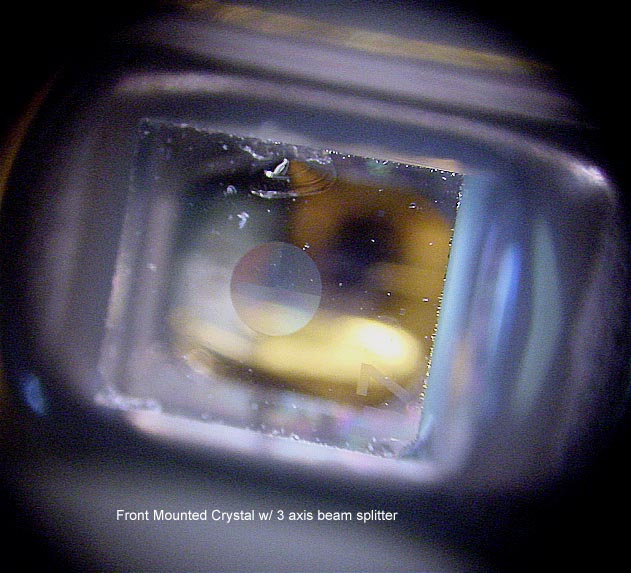
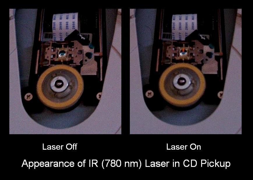
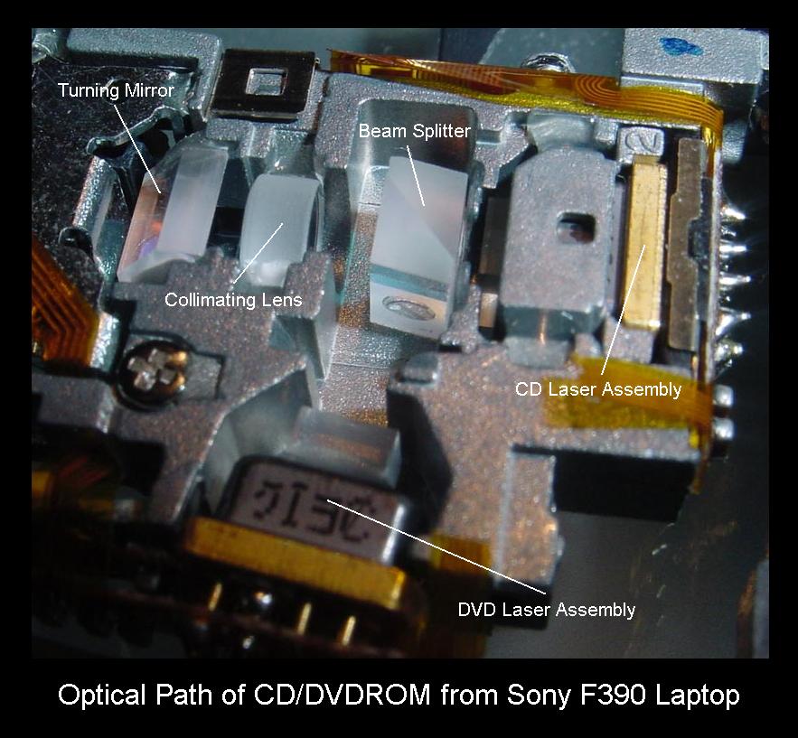
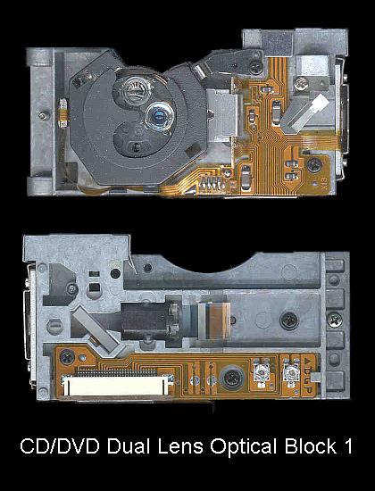
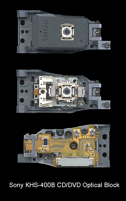
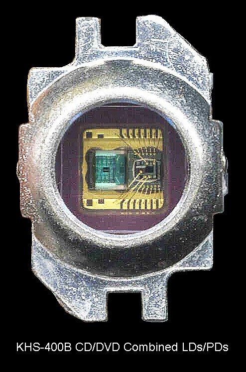
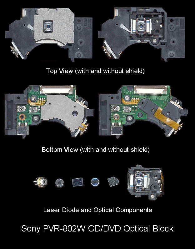
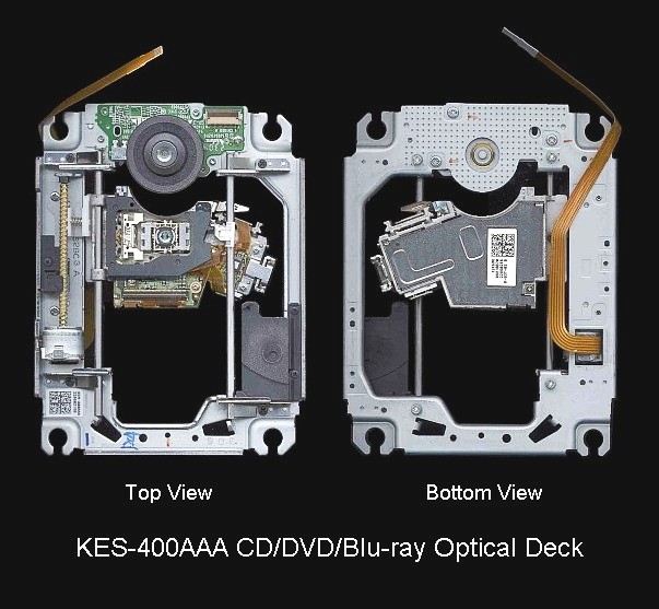
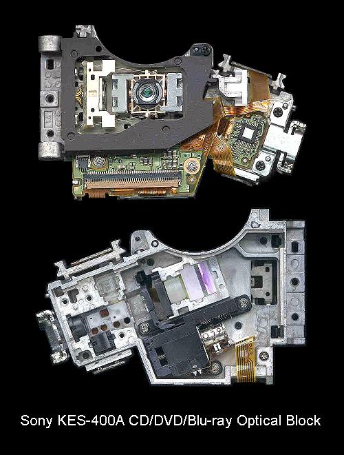
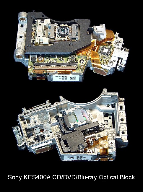
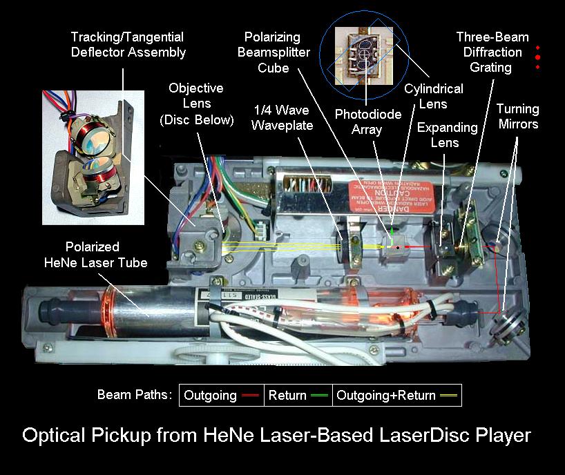
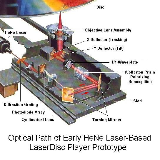